- What is the maximum data length for Inputs and Outputs in the EtherCAT communication variable list? This depends on the IO configuration. It can support over 6,000 slave devices, and the amount of outputs and inputs each module carries varies.
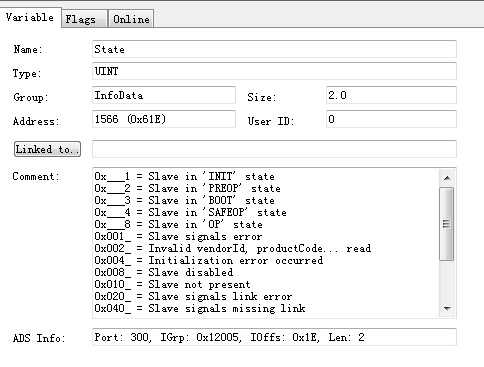
- How to read the status of a servo using EtherCAT communication to display it on the HMI? You can create a UINT variable in the PLC program and bind it to the following parameters, then display it on the interface:
- Modifying the Station (ESC Access) of the Hot Connect Module via E²PROM
Refer to Beckhoff Information System
Note: Ensure the module is online before writing to the node. - How to Modify the Sync Unit Cycle in DC Synchronization
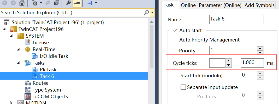
- Create a new task.
- Create a new task.
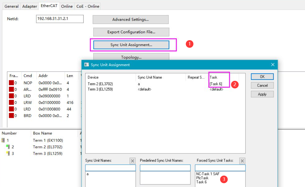
- Assign tasks to the modules you want to modify using the Sync Unit Grouping feature.
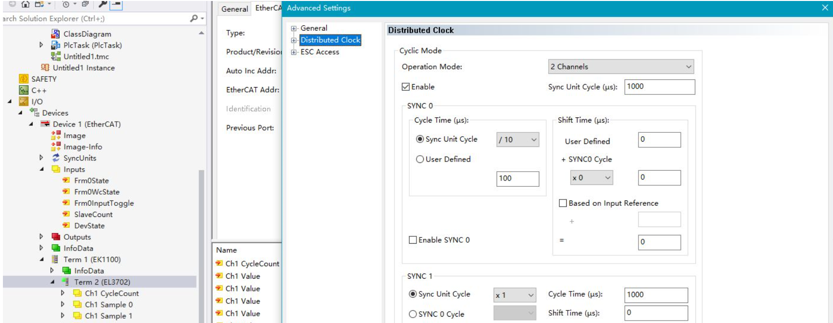
- Verify the modification results in the module's EtherCAT → Advanced Settings.
- Retrieve the EtherCAT timestamp DC System Time (DCsystime) DC Synchronization Clock (64-bit)
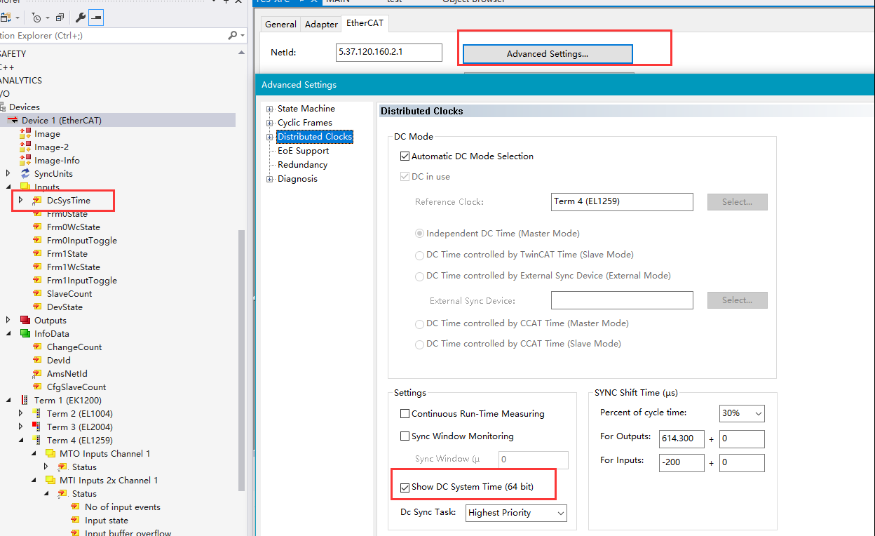
- Can variables in EtherCAT communication be of structure type? Yes, they can be structures.
- Resetting to Factory Settings for COE Parameters in EL/EP/EJ Series Modules To restore factory settings, write 0x64616F6C to directory 1011:01.


- Ensure the sensor and power are correctly connected to the EL3124.
- Verify the current with a multimeter to ensure it's indeed 5mA.

8. Introduction to Using CU2508
I. How to Use the CU2508?
II. Can the CU2508 replace the functionality of the CU2208, and provide real-time communication with enhanced capabilities?
These are not products with the same functionality; they cannot replace each other.

Firstly ,add Real-Time Ethernet Adapter

Adapter Selection for Connecting to the CU2508 Network Card

In the Ports Settings, change the Virtual Port Count to 8, set TCPIP Port to via EoE (Ethernet over EtherCAT), and modify Virtual Port Selection via to EtherCAT Switch Link Protocol (ESL).
Then, you can proceed to add the EtherCAT network.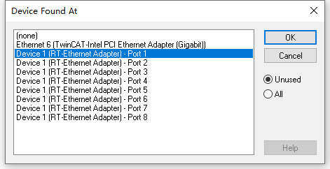
Select the port on the CU2508 for the adapter, then activate the configuration to make it effective. Once activation is complete, switch back to configuration mode. This will allow you to scan for and connect the slaves attached to the CU2508.

9. What should be considered when manually adding EtherCAT devices?
When manually adding EtherCAT devices, pay attention to the Previous Port option. In the diagram below, the EtherCAT drive is typically connected to the second port of the EK1100. However, if the drive is actually connected to the extension port of the EK1110, this mismatch can lead to activation errors.

10. How Does Information Exchange Occur Between an Industrial PC with an EtherCAT Card and the EtherCAT Slave Port on a CX5130?
The industrial PC with an EtherCAT card can interact with the EtherCAT slave port on the CX5130 just like with any typical EtherCAT slave; it can be scanned directly.
Detailed Configuration Steps:
Please refer to the documentation below for detailed configuration steps.
- Use of Internal Variables in EL High-Function Modules: After version 4024 of TC3, analog and gateway modules (not supported in regular input/output modules) have introduced a convenient feature for declaring and using variables:
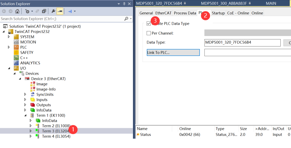

Complete the link within the PLC options of the module:

(Note in Step 1, when using the internal variable type declaration in the module, avoid adding AT% because the internal variable type has already included it in the external types.)

You can also use the "Edit" function shown in the diagram above to make modifications.

If you wish to add your own custom types, please refer to:https://infosys.beckhoff.com/content/1033/eap/1984785291.html?id=6391862396929124882