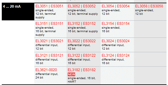
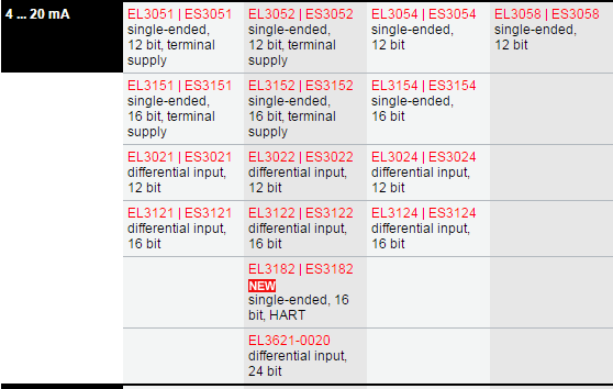
1.Here are three sensors, each with an output current of 4-20mA. Please select the appropriate input module for these sensors. 
a) Left Sensor Suitable Modules:
- EL3051, EL3052, EL3054, EL3058, EL3151, EL3152, EL3154
- EP3184-0002
- KL3054, KL3454, KL3458, KL3051, KL3052
b) Middle Sensor Suitable Modules:
- EL3051, EL3052, EL3151, EL3152
- KL3051, KL3052
c) Right Sensor Suitable Modules:
- EL3021, EL3022, EL3024, EL3121, EL3122, EL3124
- EP3174-0002, EQ3174-0002
- KL3021, KL3022, KL3122, KL3152
- IP3112-BXXX, IE3112
2. What are the model numbers for 4-20mA current analog input modules?
- EL3051, EL3052, EL3054, EL3058, EL3151, EL3152, EL3154
- EP3184-0002
- KL3054, KL3454, KL3458, KL3051, KL3052
- EL3021, EL3022, EL3024, EL3121, EL3122, EL3124
- EP3174-0002, EQ3174-0002
- KL3021, KL3022, KL3122, KL3152
- IP3112-BXXX, IE3112
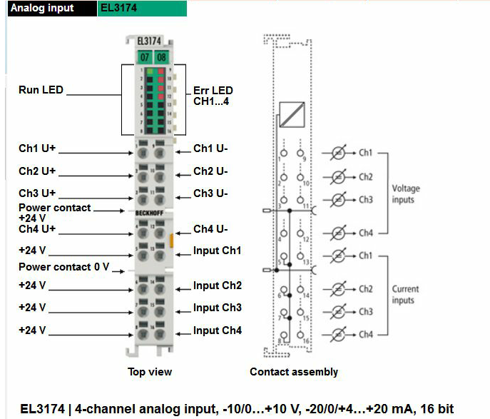
3. Are there any current-voltage universal analog input modules in the EL series?
- Yes, for example, the EL3174.
Yes, for example, the EL3174.
4. ES3004 and EL3004 Compatibility:
- Can ES3004 and EL3004 be used interchangeably?
- Yes, ES3004 and EL3004 are interchangeable. You don't need to modify anything; they can be directly replaced.
5. EL3008 Module:
- Does the analog signal connected to the EL3008 module need a resistor?
- No, it doesn't require an additional resistor. You can connect it directly as long as the signal is within the range of -10V to +10V.
6. EL3052 Module:
- How to connect a differential signal sensor to a single-ended analog input module (EL3052)?
- This method is not recommended because it can lead to significant errors. However, if you must proceed, here's how you could connect:
Can ES3004 and EL3004 be used interchangeably?
- Yes, ES3004 and EL3004 are interchangeable. You don't need to modify anything; they can be directly replaced.
Does the analog signal connected to the EL3008 module need a resistor?
- No, it doesn't require an additional resistor. You can connect it directly as long as the signal is within the range of -10V to +10V.
How to connect a differential signal sensor to a single-ended analog input module (EL3052)?
- This method is not recommended because it can lead to significant errors. However, if you must proceed, here's how you could connect:
7. Differences between EL3062 and ES3062:
- The ES3062 includes an additional front connector compared to the EL3062. However, in terms of functionality and application, they are identic
The ES3062 includes an additional front connector compared to the EL3062. However, in terms of functionality and application, they are identic
Manual:
https://download.beckhoff.com/download/Document/io/ethercat-terminals/EL36xxen.pdf
8. EL3064 Module Issue:
- You're experiencing a voltage offset where the sensor feedback voltage increases by 0.18V when connected to the EL3064 module. Here are some reasons this might happen:
- Check the Shielding: Ensure the shielding on the sensor cables hasn't been compromised or stripped. Improper shielding can introduce noise or ground loops.
- Power Supply Consistency: Verify whether the 24V supply for the analog module and the sensor are from the same source or at least share a common ground. The module's GND should be connected to the sensor's 0V.
- Sensor Output Configuration: Check if your sensor can output in the 4-20mA range. If it does, consider switching to an EL3054 module which might be more suitable for current inputs, potentially reducing voltage-related issues.
9. Wiring the EL3068 Analog Input Module:
- If your sensor outputs a positive and negative signal:
- Connect the positive lead to any of the module's input terminals.
- Connect the negative lead (or ground) to the 0V (GND) terminal on the module.
You're experiencing a voltage offset where the sensor feedback voltage increases by 0.18V when connected to the EL3064 module. Here are some reasons this might happen:
- Check the Shielding: Ensure the shielding on the sensor cables hasn't been compromised or stripped. Improper shielding can introduce noise or ground loops.
- Power Supply Consistency: Verify whether the 24V supply for the analog module and the sensor are from the same source or at least share a common ground. The module's GND should be connected to the sensor's 0V.
- Sensor Output Configuration: Check if your sensor can output in the 4-20mA range. If it does, consider switching to an EL3054 module which might be more suitable for current inputs, potentially reducing voltage-related issues.
If your sensor outputs a positive and negative signal:
- Connect the positive lead to any of the module's input terminals.
- Connect the negative lead (or ground) to the 0V (GND) terminal on the module.
10. Filtering Time for EL3102's Channels:
- The filtering time for Channel 1 (Ch1) and Channel 2 (Ch2) of the EL3102 cannot be set individually; this is documented in the infosys.
The filtering time for Channel 1 (Ch1) and Channel 2 (Ch2) of the EL3102 cannot be set individually; this is documented in the infosys.
https://infosys.beckhoff.com/content/1033/el31xx/12077411851.html?id=640564351030616497
The filter frequencies are set for all channels of the EL31xx terminals centrally via index 0x8000:15 (channel 1). All other corresponding indices 0x80n0:15 have no parameterization function!
11. Can EL3114 replace EL3112?
- Yes, it can replace it as they have the same functionality. EL3114 has 4 channels while EL3112 has 2 channels.
12. EL3124 Support for Two-Wire and Four-Wire Sensors:
- The EL3124 module supports four-wire sensors but not two-wire sensors.
13. Dealing with Inverter Interference on EL3154:
- Solution: Use a ferrite core (magnetic ring) on either the inverter lines or the feedback lines of the module.
- Will it affect data? The magnetic ring is used to reduce interference and has no impact on the signals passing through the wire.
- Installation Reference:
- "Magnetic ring installation position: generally as close to the interference source as possible. For cables exiting shielded enclosures, place the magnetic ring near the entry/exit point of the enclosure. There are roughly three methods to install a magnetic ring:
- Thread the cable through the ring and then secure it with injection molding.
- Wrap the cable around the ring a few times and secure it.
- Use a snap-on ferrite core directly on the cable. For better effect, if the ring's inner diameter allows, wrap the cable around it a few times."
14. EL3154 Status Display "OP" with Red Light:
- This could indicate either a disconnection or that the signal is out of the measurable range.
15. EL3174:
- Part I: Can EL3174 read differential 4-20mA current values?
- No, it can only read differential voltage values; current input is single-ended only.
- Part II: Can EL3174 read 4 voltage signals and 4 current signals simultaneously?
- No, it cannot do this simultaneously.
16. EL3142:
- Part I: Severe signal fluctuation when measuring current with EL3142 compared to stable readings with EL3042:
- The difference might be due to:


It's clear that the signal conversion time of the EL3142 is much faster than that of the EL3042, allowing it to capture more changes in the signal. This suggests that there's noise or fluctuations in the signal that the EL3042 can't pick up, but the EL3142 can, resulting in a signal that includes this noise.
Solution:
The conversion time parameter can be adjusted. By changing the default conversion time of the EL3142 to a value similar to that of the EL3042, you can solve this issue. The way to modify this is by adjusting the parameters in the EL3142 CoE Online, specifically at 80n0:06 and 80n:15.
![]()
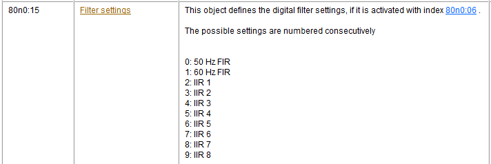
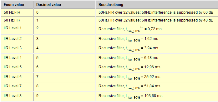
Therefore, we need to change 80n0:06 to '1' and 80n:15 to '3'.
Modification Method:
In System Manager, directly access the EL3142's CoE-Online settings, locate the corresponding parameters, and double-click to modify them.
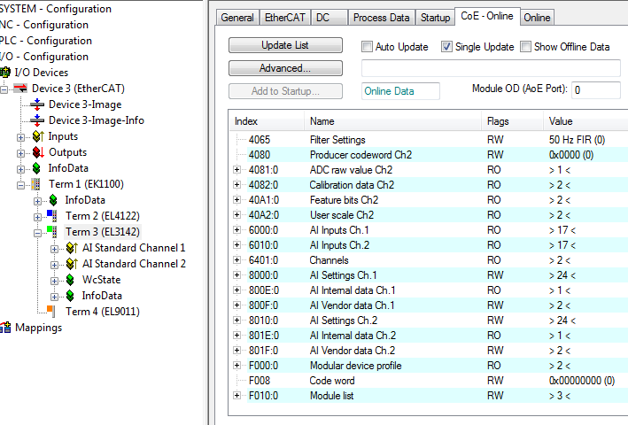
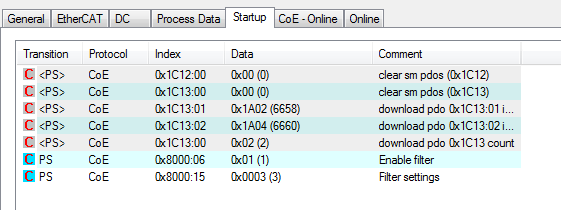
Part II: How to make the parameter settings permanent so that even if the EL3142 module is replaced, you don't need to set the parameters again?
Use the Startup functionality in System Manager.
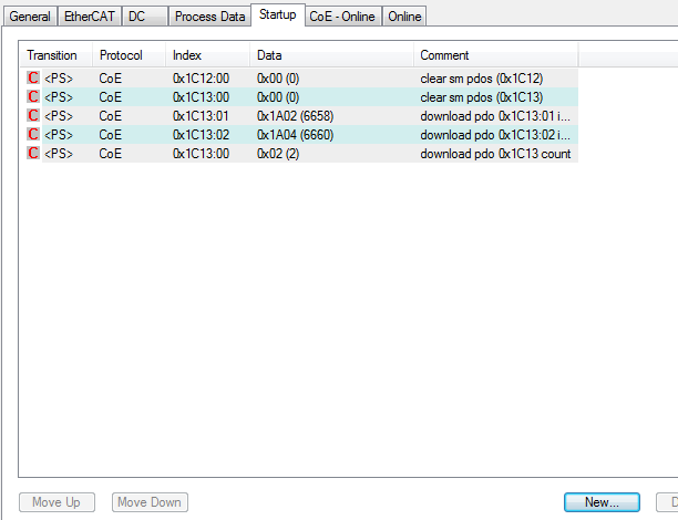
Click 'New' and in the dialog box that appears, find the parameters you need to set, then double-click to set them to the required values.
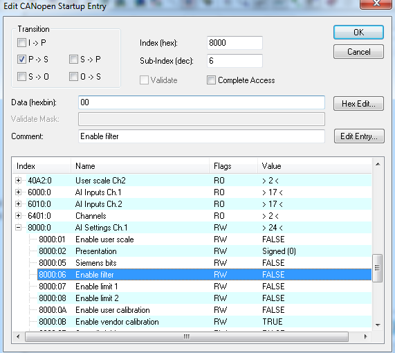
Following the same method, add these two parameter settings in the Startup section. From now on, every time the TwinCAT system starts, it will automatically write these values to the module, eliminating the need to set the module parameters individually.
17. EL3154
- What models can replace the EL3154?
- Recommended:
- EL3151, EL3152 - Single-ended input, 16-bit resolution.
- EL3121, EL3122, EL3124 - Differential input, 16-bit resolution.
What models can replace the EL3154?
- Recommended:
- EL3151, EL3152 - Single-ended input, 16-bit resolution.
- EL3121, EL3122, EL3124 - Differential input, 16-bit resolution.
18. EL3162 Module Voltage Fluctuation:
- Issue: The EL3162 module shows a fluctuation of 200mV, but when measured with an oscilloscope, the signal only fluctuates by 5mV, with ground and shield wires properly connected.
- Solution: The filtering function of the EL3162 module is disabled by default. Enable filtering by changing parameter 8000:06 (Channel 1) and 8010:06 (Channel 2) to true. The default filter is set to 50Hz but can be adjusted.
19. Module for Receiving PT100 Temperature Sensors:
- Model: EL3204.
20. EL3204
- Part I: What types of temperature sensors does EL3204 support?
- Pt100, Pt200, Pt500, Pt1000, Ni100, Ni120, Ni1000
- KT/KTY from firmware 06
- Resistance measurement from 10 Ω to 1 kΩ or 10 Ω to 4 kΩ (e.g., for potentiometer connection)
21. How Does the EL3204 Module Measure PT100 Temperature?
- The actual temperature is obtained by dividing the read value by 10. For more detailed information, refer to the link: Beckhoff Information System - EL3204.
22. Why is the Temperature Measurement Inaccurate with PT100 Sensor Connected to EL3204-0200?
- The EL3204-0200 does not support PT100 sensors by default; it supports PT1000 sensors. For specific sensor types supported by EL3204-0200, refer to the documentation screenshot.
Issue: The EL3162 module shows a fluctuation of 200mV, but when measured with an oscilloscope, the signal only fluctuates by 5mV, with ground and shield wires properly connected.
Solution: The filtering function of the EL3162 module is disabled by default. Enable filtering by changing parameter 8000:06 (Channel 1) and 8010:06 (Channel 2) to true. The default filter is set to 50Hz but can be adjusted.
Model: EL3204.
Part I: What types of temperature sensors does EL3204 support?
- Pt100, Pt200, Pt500, Pt1000, Ni100, Ni120, Ni1000
- KT/KTY from firmware 06
- Resistance measurement from 10 Ω to 1 kΩ or 10 Ω to 4 kΩ (e.g., for potentiometer connection)
The actual temperature is obtained by dividing the read value by 10. For more detailed information, refer to the link: Beckhoff Information System - EL3204.
The EL3204-0200 does not support PT100 sensors by default; it supports PT1000 sensors. For specific sensor types supported by EL3204-0200, refer to the documentation screenshot.
23. What module is used for collecting thermocouple signals, and what is the maximum distance?
- Thermocouple Module:
Thermocouple Module:

If the distance is far, it is recommended to use compensation wires corresponding to the thermocouple type. For example, if using a K-type thermocouple module, use K-type thermocouple compensation wires.
24. EL3314
- Part I: What is the error when using EL3314 for temperature measurement? If the required measurement range is 5-120°C with an accuracy of less than 1°C, how can this be achieved?
The EL3314 is an analog input module capable of connecting thermocouples for temperature measurement. At a standard room temperature of 23°C, the temperature measurement error of the EL3314 is less than ±2.0°C.
For detailed parameters on the range, error, and other specifics when connecting different types of thermocouples to the EL3314, you can refer to:https://infosys.beckhoff.com/content/1033/el331x/8929991691.html?id=3457470417005464217
For a measurement range of 5-120°C with an accuracy <1°C, consider both the sensor error and the module's error:
- Sensor Error: Temperature sensors come in thermocouples and RTDs (Resistance Temperature Detectors). Thermocouples offer a broad measurement range but lower precision, whereas RTDs like PT100 provide a smaller range but higher accuracy. To achieve an accuracy of <1°C, choosing a platinum RTD like PT100 is advisable. (For more on thermocouples vs. RTDs, see: Thermocouple vs. RTD)
- Module Error: Use the EL3204 analog input module for connecting RTDs. When measuring with PT series RTD sensors, the error is < ±0.5°C.
Thus, the recommended combination for accurate temperature measurement is PT100 with the EL3204 module.
Part II: High Temperature (over 800 degrees) Issues with EL3314:
- If the temperature readings from the EL3314 fluctuate significantly or are much lower than the actual values at high temperatures, it's likely due to the unequal potential of the four thermocouples connected to the same module.
- Solution: Short all the negative poles of the thermocouples together at the junction box side, not at the module side.
- Alternative: Consider using the EL3314-0002, which has electrical isolation between channels, for thermocouple measurements.
25. EL3318
- Are the values read by EL3318 actual values?
- The displayed value divided by 10 is the actual temperature value.
26. EL3356 & EL3356-0010
- Function and Principle of Weighing Modules EL3356 & EL3356-0010:
- EL3356: Known as a weighing or strain gauge module, it can connect to load cells, torque sensors, tension sensors, or force sensors. The basic principle is resistance bridge measurement, where mechanical force changes resistance in one arm of the bridge, creating a linear relationship between force and potential difference across the bridge arms.
- Improvements over KL3356:
- Calibration: Calibration can be done via CoE-Online; post-calibration, the output directly represents weight (KL3356 requires KS2000 for pre-rating and further PLC calibration).
- Voltage Measurement: Can measure ±12V and ±25mV signals independently.
- Digital Filtering: Includes various digital filters like notch and low-pass to reduce data jitter.
- Output Format: Outputs in real format to six decimal places, enhancing precision in calculations.
- EL3356-0010: Offers 24-bit accuracy with a 100us task support.
27. EL3356 Data Fluctuations and Noise:
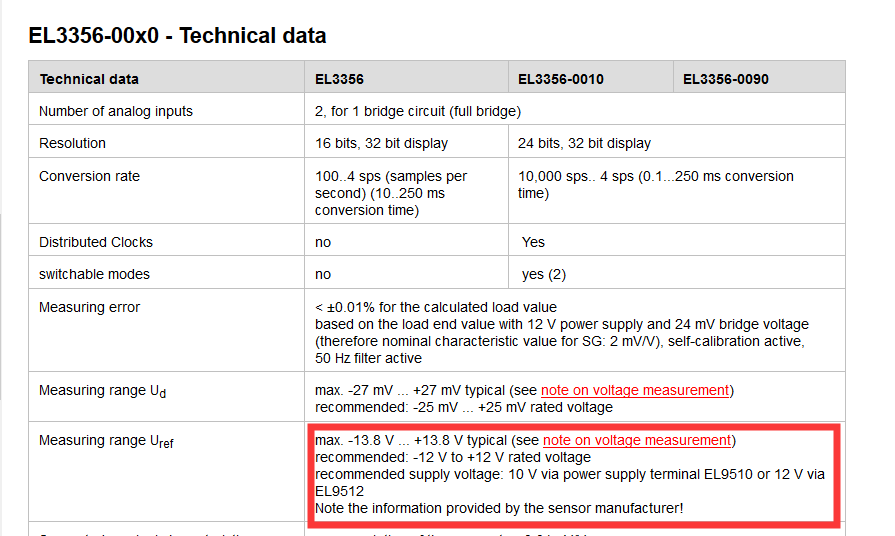
- The measuring range Uref requires a dedicated module for power supply: This implies that for accurate and stable readings, the reference voltage (Uref) for the load cell must be supplied by a specific module or power supply designed for this purpose, which reduces noise and fluctuations in the measured data.
For weighing applications, there are static weighing and dynamic weighing.
28. EL3403
- How to modify the default conversion time (default 200ms) of the EL3403?
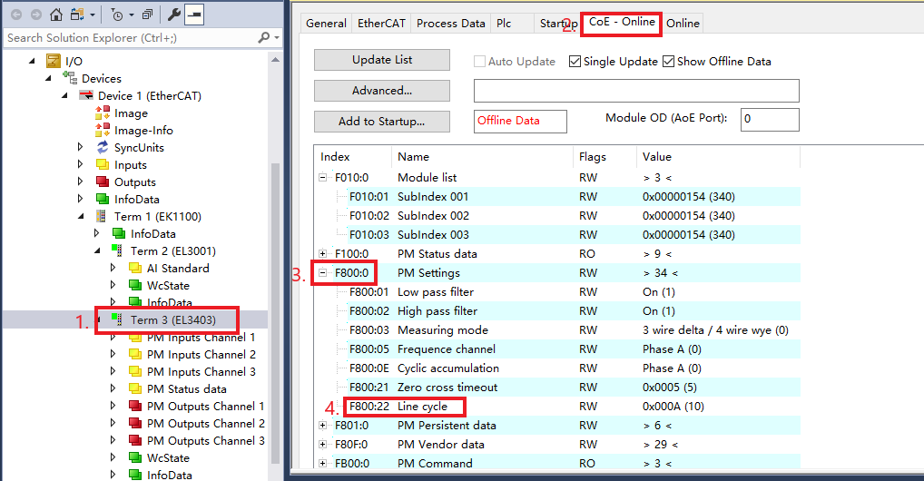
Modify Line time (index F800:22)
- At 50Hz, each sine wave period is 20ms, and by default, it's set to 10 (which means data is refreshed every 200ms).
29. EL3413
- Part I: How to wire the EL3413?
- Connect the L1, L2, L3 voltage lines to the voltage input terminals.
- For current measurement, pass L1, L2, L3 through current transformers (CTs), then connect these to the current input terminals.
- Part II: Does EL3413 require current transformers?
- Yes, it does require current transformers for current measurement.
30. EL3351
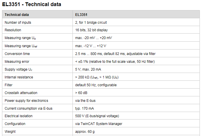
- What is the measurement range of EL3351?
- The measurement range for the EL3351 is generally specified for strain gauge measurements, typically up to ±30mV for bridge supply voltage (Uref) of 10V. However, for precise details, you should refer to the specific documentation or manufacturer's specifications, as different versions or firmware can alter these values.
31. EL3356
Calibration Steps for a 1kg Load Cell Using EL3356 to Measure mV Analog Values:
- Reset to Factory Settings: Modify CoE object 0x1011:01 to value 1684107116.
- Enable Calibration Mode: Set 0x8000:01 and 0x8000:03 to TRUE.
- Set Weight Unit: Change 0x8000:27 to 1. This sets the weight unit to grams (g) since the default is 1000 for kg.
- Gravity Acceleration: Typically, 0x8000:26 is set to 9.806650 and usually does not need adjustment.
- Enable Calibration: Set 0x8000:21 to 1.
- Set Tare to Zero: Adjust 0x8000:22 to 0, which means the tare weight is set to zero.
- Configure Filter: Set 0x8000:11 to IIR8. This provides the longest filter time, minimizing data jitter and extending the sampling time.
- Input Rated Value: Enter 1000 into 0x8000:24 ("rated value") since the sensor's maximum load is 1kg.
- Zero Point Calibration:
- Ensure no load is applied to the sensor.
- Allow the sensor to stabilize for 10 seconds without interference.
- Write "01 01" to 0xFB00:01 to perform zero calibration.
Reset to Factory Settings: Modify CoE object 0x1011:01 to value 1684107116.
Enable Calibration Mode: Set 0x8000:01 and 0x8000:03 to TRUE.
Set Weight Unit: Change 0x8000:27 to 1. This sets the weight unit to grams (g) since the default is 1000 for kg.
Gravity Acceleration: Typically, 0x8000:26 is set to 9.806650 and usually does not need adjustment.
Enable Calibration: Set 0x8000:21 to 1.
Set Tare to Zero: Adjust 0x8000:22 to 0, which means the tare weight is set to zero.
Configure Filter: Set 0x8000:11 to IIR8. This provides the longest filter time, minimizing data jitter and extending the sampling time.
Input Rated Value: Enter 1000 into 0x8000:24 ("rated value") since the sensor's maximum load is 1kg.
Zero Point Calibration:
- Ensure no load is applied to the sensor.
- Allow the sensor to stabilize for 10 seconds without interference.
- Write "01 01" to 0xFB00:01 to perform zero calibration.

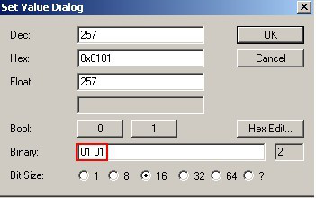
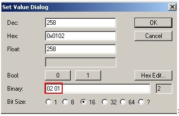
Apply Calibration Load: Place a 500g calibration weight on the sensor. It's recommended that the calibration load should be greater than 20% of the rated load.
- Enter 500 into 0x8000:28 for the calibration load.
- Enter 1000 into 0x8000:24 for the rated load.
After 10 seconds, write "02 01" to CoE object 0xFB00:01.

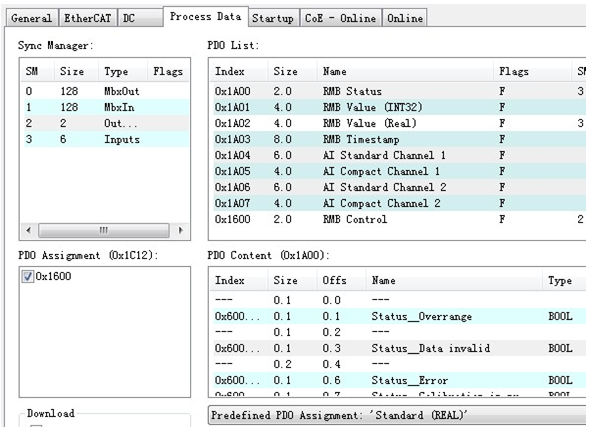

Different sensors have different technical specifications, which can lead to various measurement deviations. Factors contributing to these deviations include:
- Accuracy: How close the measured value is to the true value.
- Non-linearity: The degree to which the sensor's output deviates from a straight-line relationship with the input (applied force).
- Creep: The slow change in output over time under constant load.
If switching to voltage measurement:

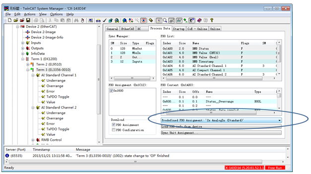

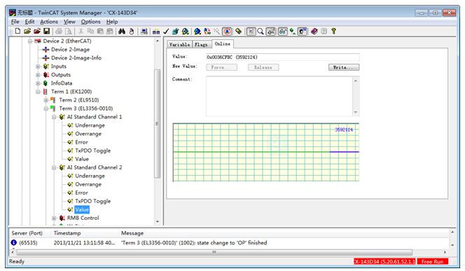
Channel 2's Value is the mV value, which has a linear relationship with force.

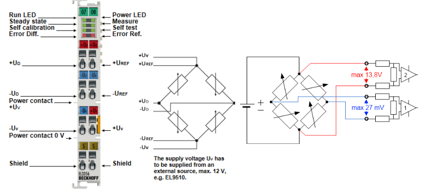
Channel 1 measurement range is -13.5 V to 0 to +13.5 V corresponding to values 0x80.00.00.00 ... 0 ... 0x7F.FF.FF.FF.
Channel 2 measurement range is -27mV to 0 to +27mV corresponding to values 0x80.00.00.00 ... 0 ... 0x7F.FF.FF.FF.
32. EL3612
- Can EL3612 connect to a single-ended sensor?
- Yes, it can, but it's not recommended since the EL3612 is designed to receive differential signals.
33. Using EL3632 with an Acceleration Sensor for Vibration Signal Measurement:
- The data can be transmitted via an OPC interface, but to form a waveform, processing in third-party software is required. However, WiFi data transmission might not be real-time, leading to data loss or discontinuity.
34. Which Module is Best for Digital Level Detection?
- The recommended module for this application is the EL3681 multimeter module.
36. EL3681
- How to Change the Signal Type Measured by the EL3681 Module from Voltage to Current?
- You need to modify the signal type in the output PDO's Mode setting of the EL3681 module.
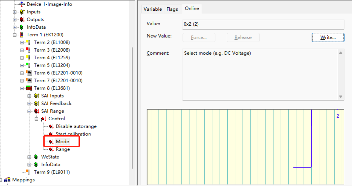
There are four types of signal measurement corresponding to variable values:
- 0 — DC Voltage Signal
- 1 — AC Voltage Signal
- 2 — DC Current Signal
- 3 — AC Current Signal
37. EL3692
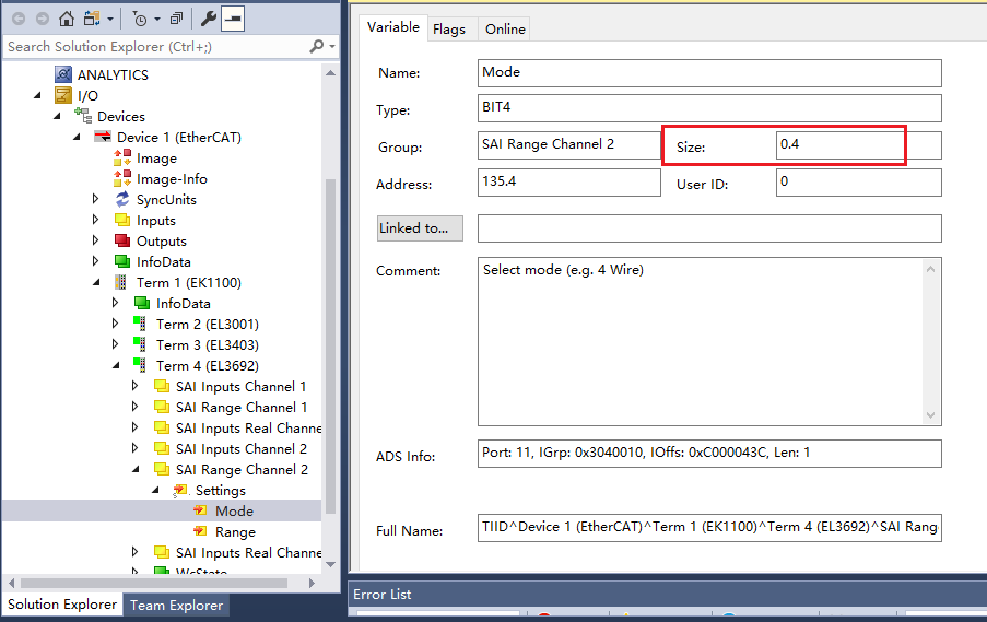
- Why can data be read from EL3692 in Free Run mode, but not when linked to a PLC variable?
- In the EL3692's Variable tab, the Size 0.4 does not mean that the linked variable must also be exactly 0.4 in size. You don't need to split the variable before linking. When you link the variable output to the mode parameter, if the variable's size is changed to a 0.4 Byte variable, you will no longer be able to read data. This indicates that the data type or size mismatch might prevent proper data acquisition when linked to the PLC variable. Ensure that the variable linked to the module matches the expected data format and size for correct operation.
