1. EL2008
Q: Does connecting a buzzer to the EL2008 require an intermediate relay?
A: You can use a relay or not, depending on whether the buzzer's rated current exceeds 0.5A.
2. EL2004
Q: What is the difference between the large numbers and small numbers on the channels of the EL2004 module?
A: The large numbers typically represent the physical channel numbers on the module, while the small numbers might indicate the logical or software-assigned channel identifiers, which are used in programming or configuration settings.

Answer: Refer to the wiring diagram that is laser-etched on the side of the module.
3. EL2024
I. Does the EL2024 module need a protective device like a freewheeling diode when directly driving a contactor?
A small coil should be fine without one, but it’s recommended to add one. The EL2024 parameter 'Breaking energy < 1.7J/channel' indicates the module can handle the reverse energy of the coil.
II. The signal light for channel 1 on the EL2024 is on, but there's no output at the output point. I'm using an EK1100 coupler.
Check the EK1100 coupler and the wiring. The issue might be with the coupler or the connection.
4. EL2032
I. Can the diagnostic function of the EL2032 module only feedback a few boolean values for short-circuit or open-circuit alarms, not the output current?
The DO module with diagnostic functions can only feedback open-circuit or short-circuit alarms; it cannot display the output current.
II. How does one determine if an output channel is short-circuited or open-circuited? How is this threshold defined?
The threshold is fixed and cannot be modified.
Detailed Information: Link to Beckhoff's documentation.
5. EL2034
I have used the EL2034 module with 2A output, and I'm concerned about the load being too heavy. Which system terminal module should I use to supply power to this module, EL9400, EL9560, or EL9100?
Recommend the EL9100 module.
6. To control the EL2252 module's dual-channel trigger output with two axes for fly-shooting, which function block is required?
You must use the XFC_EL2252_V2 function block.
7. EL2262
Can the EL2262 output module with oversampling record the conduction waveform?
You can observe the waveforms via Scope View (recommend using Array Bar Scope Project). Some file formats can record and export, while others require a professional version of Scope for export capabilities.
8. EL2502
I. Setting parameters for the EL2502 module:
- How to set the EL2502 for a 50Hz output with 50% duty cycle?
- Set 8000:07 to PWM 1-20KHZ.
- Set 8000:16 to 20000 (unit in 1us, which equals 20ms).
- Set Process data to 32767 for 100% duty cycle, 16384 for 50% duty cycle.
- How to set the EL2502 for a 5kHz output with 50% duty cycle?
- Set 8000:07 to PWM 20-20KHZ.
- Set 8000:16 to 200 (5kHz period is 200us).
- Set Process data to 16384 for 50% duty cycle.
- How to set the EL2502 for a 40kHz output with 50% duty cycle?
- Set 8000:07 to PWM 100ns frq.res.
- Set 8000:16 to 250 (40kHz period is 25us).
- Set Process data to 16384 for 50% duty cycle.
9. Can the EL2502 directly drive a stepper motor?
No, you need to use EL7031 or EL7041; the EL2502 is a PWM pulse output module.
10. EL2521
I. Where do I modify the operating frequency for the EL2521?
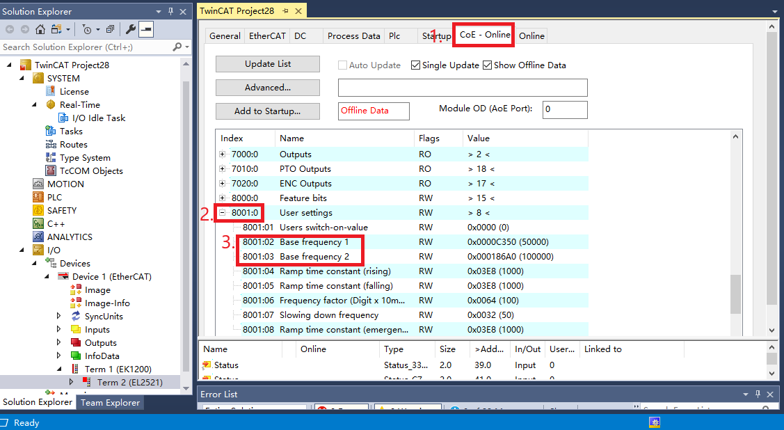
Modify the 'base Frequency' parameter under the CoeOnline tab in the I/O-Configuration for the EL2521.
How to set the EL2502 for a 50Hz output with 50% duty cycle?
- Set 8000:07 to PWM 1-20KHZ.
- Set 8000:16 to 20000 (unit in 1us, which equals 20ms).
- Set Process data to 32767 for 100% duty cycle, 16384 for 50% duty cycle.
How to set the EL2502 for a 5kHz output with 50% duty cycle?
- Set 8000:07 to PWM 20-20KHZ.
- Set 8000:16 to 200 (5kHz period is 200us).
- Set Process data to 16384 for 50% duty cycle.
How to set the EL2502 for a 40kHz output with 50% duty cycle?
- Set 8000:07 to PWM 100ns frq.res.
- Set 8000:16 to 250 (40kHz period is 25us).
- Set Process data to 16384 for 50% duty cycle.

Differences between Base frequency1 and Base frequency 2:

Output Frequency Calculation Formula:
![]()
II. How to change the current target value for the EL2521?
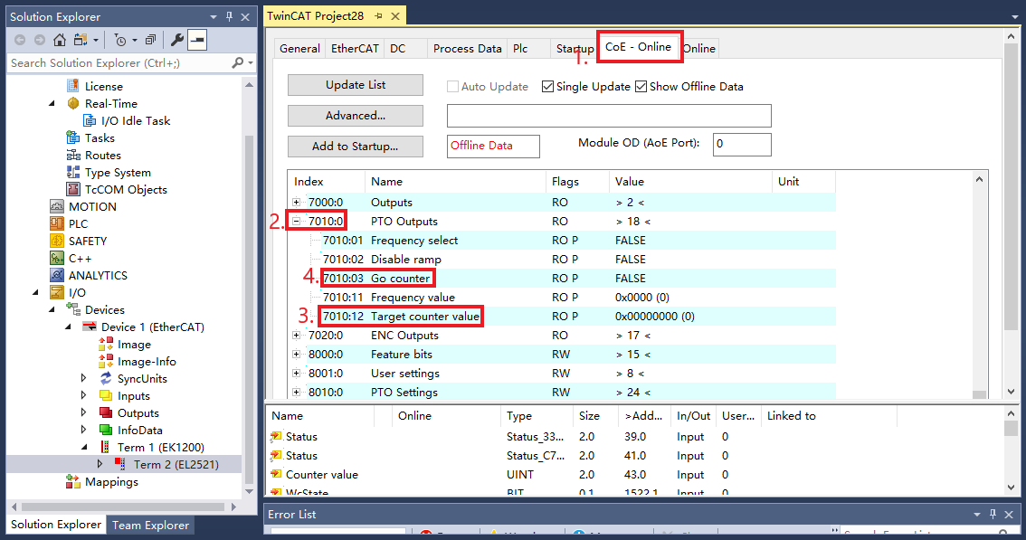
Navigate to the EL2521 module's COE-Online interface. After modifying the 'target count value', trigger the 'go counter'.

III. Can the EL2521 module output a 5V voltage?
EL2521-0000 outputs a differential 5V signal. For EL2521-0024 and EL2521-0025, the output signal is determined by an external voltage.
IV. Explanation of Using the Pulse Module EL2521 in NC (Numerical Control)
Let's define the following:
- Distance: Travel per revolution of the mechanical end; unit in mm.
- M_ratio: Gear ratio; provided by the equipment manufacturer.
- CMD_PULSE: Number of command pulses per revolution of the motor; ask the motor manufacturer.
- E_ratio: Electronic gear ratio of the drive; can be different values to enhance accuracy, with most manufacturers defaulting to 1.
- N: Rated motor speed (rpm), often 3000 rpm for Japanese motors.
Then, the module parameters are set as follows:
- Reference velocity = N/60 * Distance/M_ratio;
- Scaling Factor = (Distance / M_ratio) / (CMD_PULSE / E_ratio);
- = (Distance * E_ratio) / (M_ratio * CMD_PULSE);
- 8001:02 Base frequency1 := (CMD_PULSE / E_ratio) * (N/60);
- 8000:0E Operating mode: pulse+dir or cw/ccw or incremental code. This setting should match the drive side settings.
- 8000:06 ramp function active: false
- 8000:08 direct input mode: false
Example:
- DISTANCE = 170mm
- M_ratio = 7
- CMD_PULSE = 131072
- E_ratio = 32
- N = 3000rpm
Then:
- Reference velocity = 1214.285
- Scaling Factor = 0.00592912946428
Kv should not be set to 0, as this can cause errors. Based on current application experience, you can try setting it to 17.
11. Is there a PWM digital IO module with output current frequency? I want to control a high-frequency pneumatic valve up to 900Hz with EL2535.
I recommend using the EL2535 module, where the output type is int -32768 to 32767.
