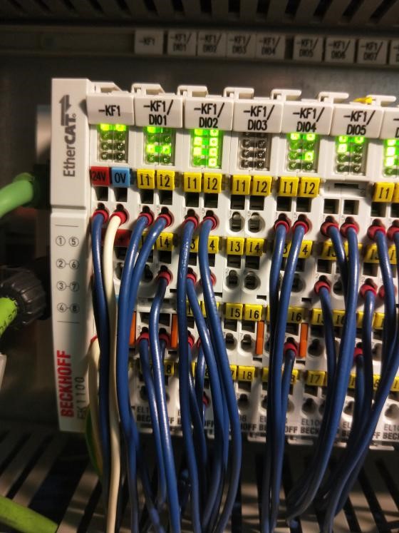
1. What do Type 1, Type 2, and Type 3 mean for Digital Inputs?
Digital input | suitable for | Level 0 „LOW“ | Transition | Level 1 „HIGH“ | |||
U [V] | I [mA] | U [V] | I [mA] | U [V] | I [mA] | ||
Type 1 | 3-wire sensors, mechanical switching contacts | -3/15 (5) | nd/15 | 5/15 | 0.5/15 | 15/30 | 2/15 |
Type 2 | 2-wire sensors, semiconductor technology | -3/11 (5) | 0...2/30 | 5/11 | 2/30 | 11/30 | 6/30 |
Type 3 | 2-/3-wire sensors, reduced power consumption | -3/11 (5) | 0...1.5/15 | 5/11 | 1.5/15 | 11/30 | 2/15 |
|
| given in min/max | |||||

- EL1904: This is a safety module that needs to be used in conjunction with EL6900 (TwinSAFE Logic Terminal) for implementing safety functions. It's designed for fail-safe digital inputs where safety is critical.
- EL1014: This is a standard EtherCAT Terminal for digital inputs without the safety features of EL1904. It's used for regular control tasks where safety isn't a requirement.
- 2mA: This is the current consumed by the integrated circuits within the EL1004 from the Up power group.
- Load: This refers to the current drawn by the load (sensor) from the Up power group.

5. Can the 3ms filter time of the EL1008 be adjusted?
No, it cannot be adjusted.
If you need a filter time of 1ms or less, you can use the EL1018, which has a filter time of 10μs.
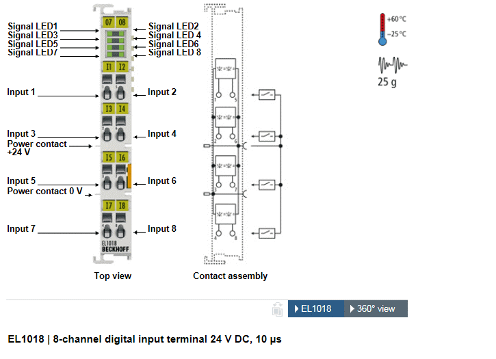
6. What is the difference between EL1008 and EL1018?
The main difference is in their filter times: EL1008 has a filter time of 3ms, while EL1018 has a much shorter filter time of 10μs.
7. What is the difference between EL1008 and EL1088?
The difference lies in the type of sensor input they support:- EL1008 is for PNP (sourcing) type inputs.
- EL1088 is for NPN (sinking) type inputs.
8. Hello, where can I download the wiring diagrams for modules like EL1088 and EL2088 from the official website?
The wiring diagrams are included in the module's datasheet:
EL1008:
https://download.beckhoff.com/download/document/io/ethercat-terminals/el10xx_el11xxen.pdf
EL2008:
https://download.beckhoff.com/download/document/io/ethercat-terminals/EL20xx_EL2124en.pdf
9. EL1144
I. Can EL9190 be used as a power supply module for EL1144 and EL2024-0010 instead of EL9512?
Yes, it can be used, but there's a difference: EL9512 takes in 24V and converts it to 12V, whereas EL9190 directly uses 12V input.
II. Will there be a problem if the signal connected to EL1144 is above 12V DC (but below 24V DC)?
No, there won't be an issue. The signal needs to be above 8.5V, but it shouldn't exceed 15V.
10. EL1252
Can EL1252 accept a 5V input?
The special version, EL1252-0050, can.
11. I am using EL1262 to collect pulses detected by sensors. After adding EL1262, there are 10 inputs on ch1 and ch2, but in your examples, each channel has more inputs?
As shown in the diagram, you can change the number of samples in the settings:

12. EL1502
I. What is the "Set Count" output variable for EL1502?
The EL1502 has an output variable called "Set Count" which is not controlled by the PLC. It automatically changes in response to variations in the input values.
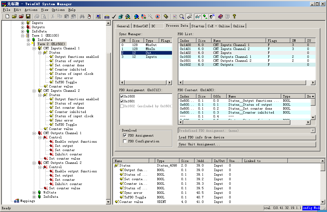
Both outputs are switched according to the counter state, so that they can be used as fast control signals for field devices.
Yes, it can. For detailed configuration, see the link:https://infosys.beckhoff.com/content/1033/el15xx/2573831819.html?id=9201960036121901292
- EL1502: This module is for simple counting. It doesn't have features specifically tailored for encoder feedback like frequency detection or direction determination.
- EL5151: This module is specifically designed for encoder feedback. It can directly read frequency values and determine whether the encoder is moving forward or backward.
- Function: The output points are used for switch outputs. The EL1502 can automatically set Output 1 and Output 2 based on the counter value.
- Implementation: For specific settings, refer to the screenshot.
15. How do you test the functionality of the EL1502, and what does "output" mean?
the gate connection can be used to control the triggering. Using the Clock1 input it is possible to implement two (32 bits) counters.
The output function is to set an output based on reaching a specific count value.
https://infosys.beckhoff.com/content/1033/el15xx/1940813579.html?id=7585778549204151841
16. EL1809 & EL1819
I. How to Choose Between EL1809 and EL1819 Based on Requirements?
- The EL1809 has a 3ms filter, while the EL1819 has a 10μs filter. Signals with a set time less than 10μs cannot be detected by either module. For signals with set times between 10μs and 3ms, use the EL1819. For signals with set times greater than 3ms, both modules are suitable.
II. What is the Input Voltage for EL1809?
- The "1" signal for the EL1809 ranges from 11-30V.
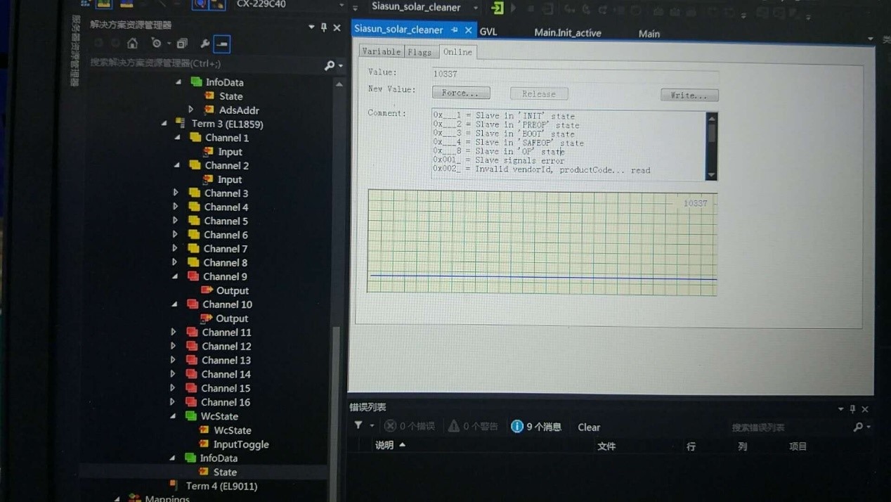
III. Why is the State of the EL1859 Module 10337 Instead of 8?
- There is no specific information provided in the given context about why the state of the EL1859 module is 10337 instead of 8. This could be due to various reasons such as a configuration error, firmware issues, or specific operational states not detailed in the documentation. Detailed diagnostics or consulting the manufacturer's documentation would be required to accurately determine the cause.
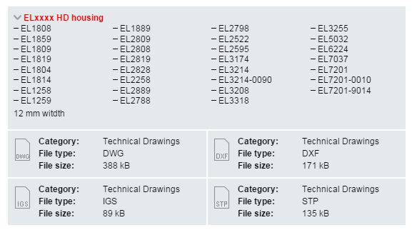
- The EL1859 is included in the ELxxx HD housing series. You can download the STP file and open it in SolidWorks.
https://www.beckhoff.com.cn/zh-cn/download/603304511
18. Does the EL1862 Support Ground Switching?
- No, it does not support ground switching. The EL1862-0010 does.
19. Can Beckhoff's EL1809 and EL2809 be Used with NPN Signals?
- No, these modules are designed for PNP signals. If you want to use NPN signals, consider using the EL1889 and EL2889.
20. EL1904
- Can the channel status of the safety module EL1904 be directly read in the PLC?
- Yes, there are input channels at the bottom of the module. You can use it similarly to the EL1004; just set up a "Link to" directly.
21. In System Manager, the online signal for the EL1008 is always 0, even though the KF01 DI 01 light is on. However, it shows 0 on the computer. What's happening here?
