- Analysis Method for EtherCAT CRC Errors
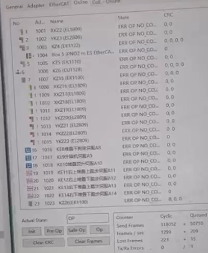
Refer to this diagram, how can we determine which module is most likely the source of the issue, and what is the basis for this determination?

TX/RX error refers to errors detected at the physical layer, encompassing issues with the network port section or the EBUS portion. These errors occur ten times in the queue section, where the queue holds aperiodic data frames. Modules that contain a mailbox section are the EL2622, EL3062, EL3044, and EL5151.
Lost frames indicate the loss of data frames, with 14 periodic data frames missing in the status. This can be challenging to pinpoint as modules such as the EL2622, EL3062, EL3044, and EL5151, which incorporate mailbox data, also include process data and can experience the loss of process data frames.
The CRC (Cyclic Redundancy Check) is processed in the automatic switching portion of the slave communication chip's port, hence CRC detection takes place in all ports utilized by the slave. This process does not occur within the data frame processing unit. The presence of CRC in an NO30 module signifies an error in a data frame. The corresponding port CRC verification sequence is illustrated in the following diagram:

The CRC verification counter for the EL3062 module increases the most, indicating a higher likelihood of issues occurring at the inlet of the EL3062.
- Function and Role of Synchronization Unit Grouping (Sync)
To prevent abnormal behavior of certain slaves from interfering with other devices or to facilitate fault source identification, the synchronization unit data grouping feature can be employed:
Many Beckhoff customers may be unaware of the function and purpose of setting up synchronization units in EtherCAT communication.
A synchronization unit, in the most straightforward sense, divides the main data frame of EtherCAT into sub-data frames corresponding to each synchronization unit.
For example, if there are 2 EL1008 modules and 1 EL3204 module, and they are defaulted to operate under a single synchronization unit (Sync), these three modules share a single sub-data frame. If one of the modules encounters a problem, the data of the other two modules cannot be refreshed. However, if two synchronization units are configured, Sync1 (for 2*EL1008) and Sync2 (for EL3204), the main data frame of EtherCAT is divided into two corresponding sub-data frames. The sub-data frames of the synchronization units do not interfere with each other. If an EL1008 encounters a problem, causing a CRC verification exception in its corresponding data frame, the other EL3204 can still function normally and its data is refreshed as usual.
It is highly recommended that when creating TSM files, multiple synchronization units should be configured.
- Function and Role of Synchronization Unit Grouping (Sync)

Grouping Method: Assign a unique Sync Unit Name to units that require independent operation. Units with identical names belong to the same data group.
Strongly recommended modules to be configured as separate synchronization units:
• Safety PLCs: EL6900, EL6910, ...
• Safety slaves: EL1904, EL2904, EP1908, ...
• Fieldbus gateways: EL6731, EL6751, EL6652, ...
• When scanning independently is feasible with OP, but anomalies occur when used alongside products from other manufacturers: Third-party drives
Emergency -> Scan Module Scanning Function
In the TwinCAT System Manager, there is a utility that can scan EL modules for initial diagnosis.
First, connect to the Beckhoff PLC controller and switch to Config or Free Run mode.
Navigate to EtherCAT -> Advanced settings -> Emergency -> Scan to scan the modules. Refer to the diagram below for illustration.
• Safety slaves: EL1904, EL2904, EP1908, ...
• Fieldbus gateways: EL6731, EL6751, EL6652, ...
Emergency -> Scan Module Scanning Function
In the TwinCAT System Manager, there is a utility that can scan EL modules for initial diagnosis.
First, connect to the Beckhoff PLC controller and switch to Config or Free Run mode.
Navigate to EtherCAT -> Advanced settings -> Emergency -> Scan to scan the modules. Refer to the diagram below for illustration.

4.Consequences of Cable
Interruption in EtherCAT Network
The output of all subsequent modules after the interruption point will become
zero.
5.Are there any
effective methods to quickly identify the faulty module?
Apart from physically unplugging each module one by one to locate the damaged
one, there are two additional methods that can assist users in determining
which module is malfunctioning:
1、Examine
the CRC and Changes counters within the EtherCAT -> Online section. If the
CRC of a specific module displays a non-zero value, it signifies that there is
an issue with the modules preceding, following, or with the module itself.
2.For CE systems, it is necessary to first access the controller's
control panel and enable the error logging function:
4.Consequences of Cable
Interruption in EtherCAT Network
The output of all subsequent modules after the interruption point will become
zero.
5.Are there any
effective methods to quickly identify the faulty module?
Apart from physically unplugging each module one by one to locate the damaged
one, there are two additional methods that can assist users in determining
which module is malfunctioning:
1、Examine
the CRC and Changes counters within the EtherCAT -> Online section. If the
CRC of a specific module displays a non-zero value, it signifies that there is
an issue with the modules preceding, following, or with the module itself.
By
default, the save path for the error log is set to "My Computer" and
the file is named "tcsyslog.txt":

If
you are using Windows 7/10, you can click on the TwinCAT icon in the
bottom-right corner, navigate to Tools –> EventViewer to check if there are
any error logs recorded.
6.What should I do if the embedded controller is
unable to scan subsequent modules?
By
default, the save path for the error log is set to "My Computer" and
the file is named "tcsyslog.txt":
If
you are using Windows 7/10, you can click on the TwinCAT icon in the
bottom-right corner, navigate to Tools –> EventViewer to check if there are
any error logs recorded.

It could be a fault with
the E-BUS or a poor contact between modules. In case of poor contact, you can
try reseating the module or firmly pressing down on both sides (this operation
should be performed while the power is off).
Alternatively, you can connect to the
EK1100 via the controller's Ethernet port and use the EK1100 to test the
modules. If the scan is successful, it is likely that the fault lies with the
E-BUS of the controller itself.
6.What is the issue when
setting a digital output to true but the output keeps flickering?
The cycle time of the Task is set too long. It is recommended to set it to less
than 100ms.
7.When running the
online controller, a popup error 1861 appears;
during this time,
executing a scan results in error 179
8.Runtime error: The
slave displays "received invalid DC timings! check device state for INIT,
communication error '1823'".


9. In TwinCAT 3, to add the Changes
counter for observation in the EtherCAT network under IO in the Online tab,
simply select the EtherCAT network from the Online tab and then choose
Properties.

In the pop-up dialog box, tick the box next to "Show Change Counters (State Changes/Not Present)" on the right side, and then click OK to confirm.

However, in version 4024.7, the aforementioned options will not be available when right-clicking (as shown in the figure below).


10. What does it mean when some of the
"repeat sup" entries in "sync unit assignment" have a cross
(X) mark?
Question: What does the
cross (X) mark in "repeat sup" under "sync unit assignment"
indicate?
Answer: The X indicates a digital module.

11.How to automatically calculate
E-bus current consumption?
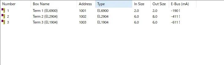
To calculate E-bus current consumption, first configure the modules according
to the system requirements during the configuration process. Then, in Device X,
under the EtherCAT tab, you can find the E-bus current consumption statistics
as shown in the figure below. This allows for convenient access to information
on E-bus current usage.
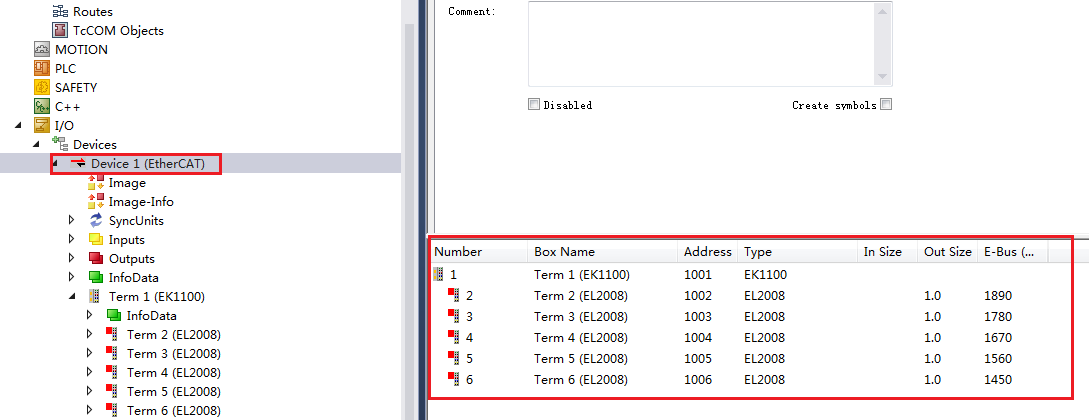
When the current of the E-bus is insufficient, it is necessary to add an E-bus power terminal module, such as EL9400, EL9410, etc.
When the current of the E-bus is insufficient, it is necessary to add an E-bus power terminal module, such as EL9400, EL9410, etc.
12. Methods to Identify Modules with State Not Equal to OP
Method 1:
Create an array where each element is linked to the State value of individual
modules. Check if the State value is not 8 (OP) to identify modules not in OP
state.
Speed of Information Acquisition: Fast
within the current cycle.
Suitable for: Fixed configurations to locate problem points.
Limitations: Cannot simultaneously obtain information such as disconnection
status.
Method 2:
Function Block FB_EcGetAllSlaveStates,
How long does it take to obtain
values?
The PLC invokes this function block and obtains data within two Task cycles,
with minimal impact on the CPU.
What values are obtained?
It can retrieve deviceState and linkState information.
DeviceState: INIT, PreOP, BOOTSTRAP, SAFEOP, OP
13.Summary of SetSlaveState
(1) FB_EcSetSlaveState can be used to individually control the restart of
an EtherCAT slave. When the PLC utilizes this module to issue commands to the
EtherCAT master, the master integrates these commands and sends them to the
slave, potentially causing an increase in CPU utilization.
(2) Different modules take varying amounts of time to transition from
INIT to OP. Digital modules typically have a shorter transition time, while
analog modules take longer, and communication modules such as EL6731 and EL6751
may require approximately 100 cycles.
(3) The performance of the controller CPU and the number of modules set
to OP can have varying impacts on the CPU. For instance:
- CX1020, with a 1ms Task and 16
slaves, running SetAllToOp can instantaneously reach over 9692 (96%)
utilization, with a full-scale value of 10000. Running SetOne, on the
other hand, can reach around 1300 (13%) utilization.
- CX5020, with a 1ms Task and 30
slaves, running SetAllToOp can exceed 15000 (150%) utilization, despite a
full-scale value of 10000
14.Impact on Other Modules within a Synchronization Unit Group When WcState of a Unit is 1
When the WcState value of a synchronization unit equals 1:
- DI/AI values remain unchanged
from the previous cycle.
- DO/AO values depend on the
State of the module itself:
- If the module's State is 8,
it can output normally according to the PLC program.
- If the module's State is not
8, after the watchdog timer expires, the module's output is set to 0.
15.How IO is Refreshed in EL Modules During SafeOp, PreOp, and INIT
During SafeOp:
- Input values are refreshed
periodically.
- For digital outputs, there is
no output after the set watchdog time expires.
- Analog outputs are immediately
set to 0, but the actual output voltage reaches 0 within 20ms (turn-off
time).
During PreOp and INIT:
- AI is immediately stopped from
refreshing.
- AO channels are immediately
set to output 0, with the actual voltage reaching 0 within 20ms (turn-off
time).
16.EL Module Status Alternately Flashing Between SafeOp, init_err, OP,
and INIT
The fault symptom arises when a variable mapped to a module is allocated to a
large task instance (100ms). Deleting the mapped variable restores normal
operation for all modules.
- The EL module status
alternates between flashing "safeop init_err," "op,"
and "init."
The fault phenomenon arises due to a variable mapped to a module being
allocated to an instance of a significantly large task (100ms). Upon
removing the mapped variable, all modules return to normal operation.
The fault phenomenon arises due to a variable mapped to a module being allocated to an instance of a significantly large task (100ms). Upon removing the mapped variable, all modules return to normal operation.
18.
Error Reported During EtherCAT Module
Switching to OP: "AL status '0x0012' read and '0x0004' expected. AL Status
Code '0x001e - Invalid SM IN cfg'"
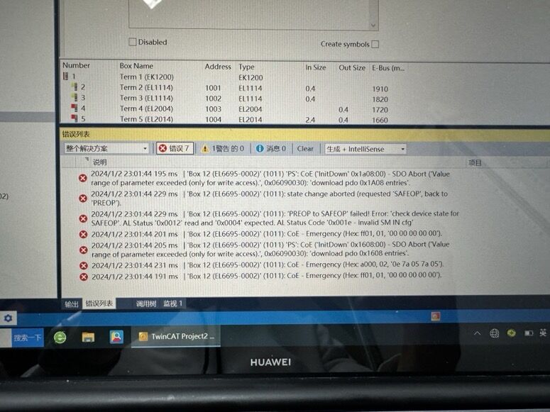
Taking the
EtherCAT bridge module EL6695 as an example, after the master station
configuration is completed, the PDO (Process Data Object) scanned from the
slave station does not match that of the master station
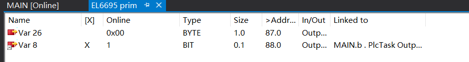
When
adding input and output variables to the Prim end of EL6695, selecting Bool is
not allowed, as it would cause the El6695Box scanned by the Secondary end to
read Bool variables as bits, resulting in inconsistent PDO data sizes and
preventing the Secondary end from entering OP mode.


Solution
1: Add Byte variables instead of Bool variables and bind them to the Bool
variables in the PLC. (This is because both Byte and Bool occupy 8 bits in
TwinCAT3.)
Solution
2: Add Bit variables instead of Bool variables and bind them to the Bool
variables in the PLC. (This has been tested and found to be feasible, however,
it is still recommended to use Solution 1 with Byte variables.)

Taking the
EtherCAT bridge module EL6695 as an example, after the master station
configuration is completed, the PDO (Process Data Object) scanned from the
slave station does not match that of the master station
When
adding input and output variables to the Prim end of EL6695, selecting Bool is
not allowed, as it would cause the El6695Box scanned by the Secondary end to
read Bool variables as bits, resulting in inconsistent PDO data sizes and
preventing the Secondary end from entering OP mode.
Solution
1: Add Byte variables instead of Bool variables and bind them to the Bool
variables in the PLC. (This is because both Byte and Bool occupy 8 bits in
TwinCAT3.)
Solution
2: Add Bit variables instead of Bool variables and bind them to the Bool
variables in the PLC. (This has been tested and found to be feasible, however,
it is still recommended to use Solution 1 with Byte variables.)
19.
When scanning I/O with the EK0000
module, the module fails to be recognized properly, and an activation
configuration error 1798 (0x706) occurs, accompanied by "IoOpen
failed" and the module status indicates "int_err". A resolution
method involves manually writing to the EEPROM.
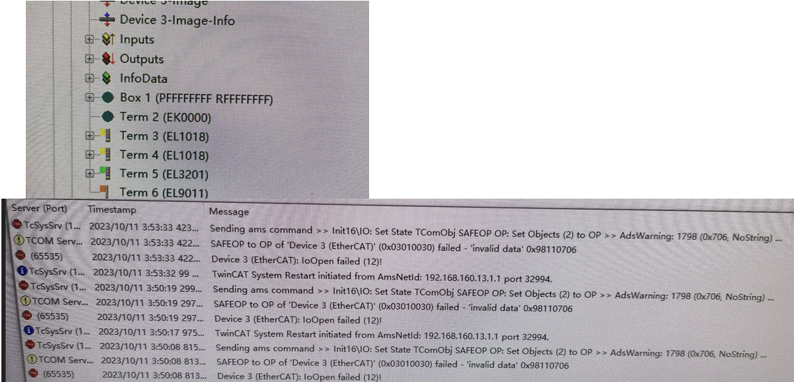
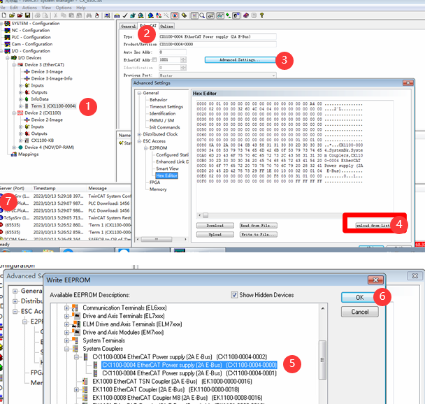
Solution: Attempt to manually write the EERPOM
on the abnormal slave station using the original configuration, then rescan the
module. If it enters the OP state, it indicates success. If the write operation
prompts an operation not allowed or the error persists as "int_err",
please contact Beckhoff personnel for further assistance.
Solution: Attempt to manually write the EERPOM on the abnormal slave station using the original configuration, then rescan the module. If it enters the OP state, it indicates success. If the write operation prompts an operation not allowed or the error persists as "int_err", please contact Beckhoff personnel for further assistance.
20.How to maintain
output state when an EtherCAT module experiences communication abnormalities?
In the slave's configuration page, navigate
to: ethercat → advance settings → behavior → watchdog → set sm watchdog. Check
the box and set the value to 0.
Alternatively, in the
Behavior section under General, locate WatchDog:
Check the box for Set SM WatchDog and set the value to 0.

21.What is the meaning
of AL Status Code?
The AL Status Code is diagnostic information at the software level related to
EtherCAT state operations. Once a slave fails to enter the correct state as
required by the master, an AL status code will be reported in the slave's
register word.
22.In the Topology View
interface, what do the small circles under each module represent?
The small circles under each module in the Topology View interface indicate the
presence of CRC (Cyclic Redundancy Check) errors on the module's ports A, B, C,
or D.

23.What does ERR SAFEOP indicate?
The presence of "SAFEOP to OP failed!" in the software error list
indicates a state-related issue. Verify the EtherCAT slave state by accessing
the online status through the device's (EtherCAT) online interface.
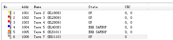
- If it appears in the status bar of the EL module,
please first confirm that the E-bus power supply is sufficient. If power
insufficiency is detected, please add power supply modules to the
insufficient locations.
2.
If this error appears on all
modules, please verify the controller's current license to ensure it includes
the necessary IO control level, or check if the license expiration date has
passed (a discharged controller battery can reset the system time, requiring
battery replacement).
3.
For an AX5000 displaying
"safeop err preop init_err", check the safety board settings and
safety signal status in the servo's DriveManager under the Safety Option. If
signals are missing, trace back to the safety logic for confirmation. (For non-servo
devices encountering "preop init_err", it's typically due to damaged
Ethernet cables or external hardware anomalies. Hardware additions/subtractions
may be necessary for troubleshooting.)
4.
If modules were previously
working normally but now multiple modules display "safeop"
accompanied by other errors such as "init" or "mis_lnk",
scan the configuration to confirm proper power-up and wiring of the actual
hardware.
5.
(Duplicate of previous point,
but with additional information) If modules were functioning normally but now
display "safeop" under a new configuration, specifically for
high-function modules, attempt to initialize the module by navigating to the
module's CoE Online and entering 16#64616F6C into 1100:01.
6.
If modules were functioning
normally before, and the issue resolves after a restart but recurs
occasionally, or if step 4 does not resolve the issue, it is recommended to
replace the modules with spare parts.
7.
If the system can achieve OP
status in free-run mode but encounters errors upon activation, the issue is
likely related to configuration. For third-party slaves, please verify their
status and ensure proper configuration (contact the manufacturer for
description files and configuration documents compatible with the current
software version). If the third-party product functions normally when used
independently, focus on the integration and configuration aspects.
24.How to Configure the WcState Fault
Tolerance Period in TwinCAT 3?
In
actual field applications, issues often arise due to invalid data (WcState=1),
such as NC error 4466, which can sometimes be challenging to resolve on-site.
To address such problems, one approach is to appropriately increase the WcState
fault tolerance period. It's important to note that invalid data issues are
typically caused by communication issues, and this method does not address the
communication problem itself.
For
instance, when encountering NC error 0x4466 (17510),
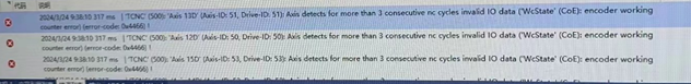
Upon
reviewing the help documentation, we have discovered that error 4466 is
actually triggered by three consecutive NC cycles with invalid data
(WcState=1).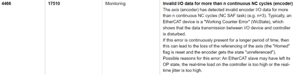
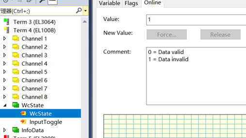
The field
input module is in an OP (Operational) state with the input light illuminated,
yet there is no input registered in the program. This is also attributed to
invalid data (WcState=1).
Upon
reviewing the help documentation, we have discovered that error 4466 is
actually triggered by three consecutive NC cycles with invalid data
(WcState=1).
The field
input module is in an OP (Operational) state with the input light illuminated,
yet there is no input registered in the program. This is also attributed to
invalid data (WcState=1).
Method for Configuring
TwinCAT 3 WcState Tolerance Cycles
To adjust the frequency of invalid WcState
data, navigate to the corresponding Sync Unit and tick the box labeled
"Individual WcState Tolerance Cycles" (this setting takes effect
after activation of the configuration). Through this option, you can set the
WcState Tolerance Cycles. For instance, if you set WcState Tolerance Cycles to
2, it means that only when two consecutive cycles have invalid WcState data
will a value of 1 be written. The maximum number of cycles that can be set is
16. Different Sync Units can have their individual WcState Tolerance Cycles
configured.
Note: Some third-party servos or slaves have
corresponding settings within their internal configurations. If TwinCAT3 is
configured with this setting, the corresponding fault tolerance values of the
third-party drives should also be increased accordingly.
25.The routing keeps disconnecting and
then automatically reconnecting. How should I handle this issue?
1.Loose
Ethernet cable connector or there is interference.
2.Communication
timeout.
26.EtherCAT Communication Instability
This issue is typically resolved by using an Intel network card that is
supported on the compatibility list.
If the network card is not on the supported list, there is a risk of
encountering a blue screen error during hardware scanning or when activating
the configuration. If the blue screen is avoided, communication errors may
occur frequently.
I have tested two computers that previously experienced blue screens, and after
reinstalling the operating system (with drivers installed), installing TwinCAT
2232 ran without issues. Currently, I am running EtherCAT on my laptop with
50us tasks without any problems.
It is recommended to use a clean operating system with all necessary patches
and updates applied.
27.What do the slave
statuses "OP Link_Mis A" and "OP Link_Add B" displayed by
the TwinCAT master station mean?
It suggests a wiring error on your side. The A port, which is supposed to be
connected to an Ethernet cable, is not actually connected, while the B port,
which does not require a connection, is mistakenly wired.
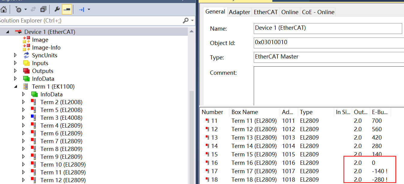
28.The E-bus voltage of
the first module after the coupler displays a negative value.
When using an EL module directly connected to a CX embedded controller, the
power supply wiring and voltage measurements are all normal, but the first
module displays a negative E-bus voltage as shown in the image below. At this
time, the safety module cannot be added to the Safety project.
It was discovered that
the coupler module is not being displayed, whereas the CX embedded system's
built-in coupler should be shown as EK1200, but it is missing.
At this point, the best approach would be
to check if any EtherCAT description files, particularly those that come with
TwinCAT, have been deleted from the debugging PC. Update the description files
to ensure that all built-in EtherCAT description files are present. After doing
so, reopen the software and scan for IO, which should then function normally.
The storage paths for
TwinCAT3 description files are:
C:\TwinCAT\3.1\Config\Io\EtherCAT
And for TwinCAT2
description files:
C:\TwinCAT\Io\EtherCAT
29.What functionality
can be used to diagnose when the actual task cycle time exceeds the preset
time?
The watchdog function of the bus terminal module can be configured to detect
instances where the actual cycle time exceeds the preset time. If the module
fails to receive valid process data from the controller within the preset time,
the watchdog will trigger an alarm after 100ms.
The watchdog function can be activated using KS2000 or through TwinCAT. For
Profibus, this function can be set up on the Profibus master station.
30.What causes the
EtherCAT state machine to periodically transition from NO_COMM to OP every 5-10
minutes and then recover?
Possible Cause: The use of single-core wires, where alternating friction can generate CRC errors, and slow detachment may lead to a probability of losing 10 frames. (Shortening the scan cycle has minimal impact.)
Solution: A faulty connector in a certain section of the Ethernet cable resulted in the EhertCAT master station continuously losing 10 frames and restarting. The issue was resolved by replacing the Ethernet cable.