How to Use the TM Count Counter Module of ET200SP ?
In industrial settings, there are numerous pulse signals present, such
as those from incremental encoders and flow meters. Acquiring these
signals requires the use of a High Speed Counter (HSC). In today's
article, we will introduce the TM Count 1x24V high-speed counter module
for the Siemens SIMATIC ET200SP.
The "Count" in TM Count 1x24V stands for "counter," and "1x24V"
indicates that it has one counting channel with an input voltage of 24V
DC. Its appearance is as shown in the following image:
TM Count 1x24V has the following features:
- Supports signals A, B, and N from incremental encoders.
- Three digital inputs: DIO, DI1, and DI2.
- Two digital outputs: DQ0 and DQ1.
- Supports software gating and hardware interrupts.
- Counting range: 32 bits (4 bytes), configurable.
- Default channel measurement frequency: 200 kHz, with a maximum of 500 kHz.
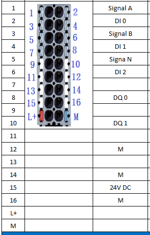
For TM Count 1x24V, a base unit (Baseunit) is required. Taking BU15-P16+AO+2B as an example, the pin definitions for the module are as follows:
Next, let's introduce the hardware configuration of TM Count 1x24V:
Firstly, we add the interface module for ET200SP to the project: IM155-6 PN, as shown in the following image:
Then, in the hardware catalog, navigate to [Technology modules] - [Counting] and locate the [TM Count 1x24V] module.
Double-click or drag [TM Count 1x24V] to install it into the empty slot of ET200SP, as shown in the following image:

After hardware installation is completed, the module needs to be configured. TM Count supports the following four configuration methods:
In this example, we're using a CPU 1515-2 PN and ET200SP to build a Profinet network, with the TM Count located in the ET200SP. First, in the hardware configuration, set the operating mode of the TM Count module to "Operating with technology object 'Counting and measurement'," as shown in the following image:
Then, within the current CPU in the project tree, locate "Technology
Objects," double-click "Add new object," as shown in the following
image:
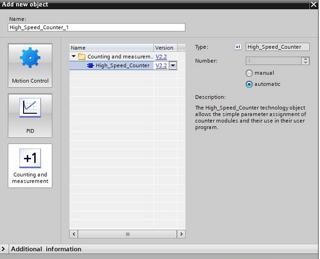
In the dialog box that appears, select "Counting and measurement," then
click to select "High_Speed_Counter." You can either use the default
name or rename it as needed. See the image below for reference:
After clicking "OK" to confirm, you will see the newly created
high-speed counter object [High_Speed_Counter_1] in the project tree, as
shown in the image below:
Double-click to open its parameter configuration page, where you'll notice that the "Module" column is displayed in red, indicating that we need to first configure the corresponding technology module for this technology object. See the image below for reference:
Click on the "Browse" button on the right-hand side. In the dialog box that appears, locate the counter module TM Count for the ET200SP, as shown in the image below:
After clicking "OK," the hardware module for the technology object is configured.
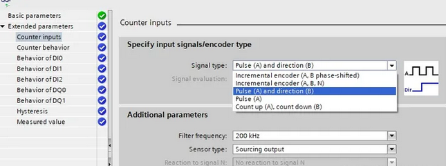
Next, proceed to configure the extended parameters. In the "Counter inputs" section, select the type of pulse signal to be used, including the following types:
- Incremental encoder (A, B)
- Incremental encoder (A, B, N)
- Pulse A and direction B
- Pulse A
- Add counter A and subtract counter B
The TM Counter module supports three digital inputs (DI), which can be configured as hardware gate start/stop signals or used as regular digital input signals. It also has two digital outputs (DQ), which can be used for pulse count comparison. When conditions are met, the channels will have outputs.
In the "Measured value" section, choose "Frequency," "Period duration," or "Velocity" based on the actual situation, as shown in the following image.
Alright, that's all for the introduction to the TM Counter's process configuration. If you have any other questions or need further assistance, feel free to let me know.