The backplane modules of the Siemens ET200S series PLC, including the Terminal Module, Electronic Module, and Power Module, are separate and offer various types for selection. Familiarity with the types of backplane modules contributes to ensuring the correctness of circuit design, enhancing hardware utilization, and cost savings. In this article, we will specifically discuss the first part of the ET200S backplane modules—the Power Module.
Functionally, ET200S backplane modules can be divided into Power and Electronic Module categories. Based on the number of connecting terminals, backplane modules come in 2X2 (two rows, each with two), 2X3 (two rows, each with three), 2X4 (two rows, each with four), and 2X6 (two rows, each with six) configurations. Regarding the method of terminal fixation, they can be classified as Spring, Screw, and Fast Connection.
The naming of backplane modules follows a specific pattern, providing information about the module's classification. For instance, in the name "TM-P15S22-01," "TM" stands for "Terminal Module," "P" indicates Power, "15" represents the module's width as "15mm," "S" denotes the fixation method as Spring, "22" signifies the number of terminals as "2X2 (two rows, each with two)," and "01" indicates the absence of a connection to the AUX1 bus. The physical appearance of the "TM-P15S22-01" module is illustrated in the accompanying image.

In the previous description, you may not have grasped the statement "01 indicates the absence of a connection to the AUX1 bus." What is the "AUX1 bus"? In fact, it is a connecting line beneath the backplane module that can serve as a common ground or for other purposes, depending on the designer's intent. To better understand "AUX1," let's examine another power module: TM-P15S23-A0, as depicted in the following image:

In the provided image, the connecting line indicated by the number "5" represents the "AUX1" bus. It can be observed that this bus is externally connected to the "A4" and "A8" terminals. However, it is important to note that the AUX1 bus in this module only extends to the right; it does not have pins on the left side (no pins are inserted), and this is the reason for the last letter in its name being "A0."
Are there modules with AUX1 buses extending on both sides? Yes, there are. One such module is named "TM-P15S23-A1," and it has pins on the lower left corner. Its schematic is depicted below:

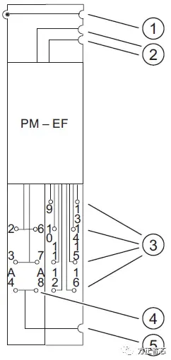
In addition, there is another backplane module designed to provide power for the fault-tolerant safety module (PM-E F 24 VDC): TM-P30S44-A0, as shown in the following image:
This module appears to be distinct in its specifications, and its nomenclature likely indicates its characteristics and features related to power supply for fault-tolerant safety applications. The accompanying image provides a visual representation of the TM-P30S44-A0 module.
From its nomenclature, it is evident that the module has a width of 30mm, utilizes the spring fixation mode (S), and serves as the starting module for the AUX1 bus (A0). The "3" section is designated for connecting to power modules, such as the fault-tolerant safety power module depicted in the following image:
Regarding the first part of the Siemens ET200S backplane modules – the Power Module, we conclude our introduction here. In the next article, we will delve into the second part – the Signal Module (Electronic Module) category of backplane modules.
For further reference, please refer to the article:
"Understanding Fail-Safe Systems in Five Minutes"