The use of PLC modules can generally be divided into two parts: first, correct electrical connections must be made on the hardware, and second, corresponding configuration (hardware setup) and programming need to be performed in the software. In the article "How to Use SM1232 to Output Analog Signals to the Actuator," we discussed the electrical wiring of the S7 1200 analog output module SM1232. In this article, we will focus on the hardware configuration and software programming of SM1232.
In the Hardware Catalog of TIA Portal V13, locate the analog output module "AQ" and expand the subdirectory. There are two types: "AQ 2x14 BIT" and "AQ 4x14 BIT." Each type has two versions. The appropriate version should be selected based on the actual hardware requirements of the project, as shown in the following image:

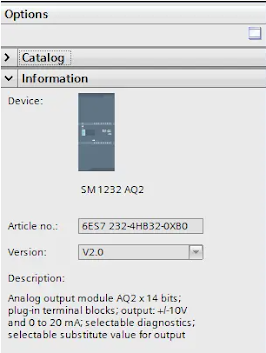
Here, we choose the two-channel type (AQ 2x 14 BIT), the second version. The information for this version is as follows:
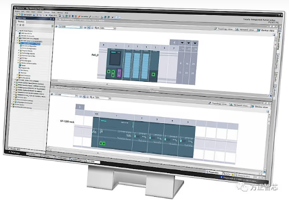
After double-clicking, you can add it to the right of the CPU in the hardware configuration, as shown below:

In its Properties box, we first need to configure the type of analog output. Click on the respective channel, such as "Channel 0," and in the "Analog output type" on the right, you can choose between "Current" or "Voltage." Assuming we choose "Current," in the second row, you can select the "Current range," with options of "0-20mA" and "4-20mA." Typically, "4-20mA" is chosen (Reference: Why is the 4-20mA current signal widely used for analog signals in industrial settings?).

Additionally, if you need to change the output address of the analog signal, you can modify it in the "I/O address" section (though you can also use the default address), as shown below:

After completing the hardware configuration, the next step is software programming. We need two instructions: SCALE_X and NORM_X. The following image shows the list of instructions:

Firstly, we add the "SCALE_X" instruction to the project's function block (FB). This instruction converts the engineering value into an analog value. Since we have chosen current output, which is unipolar output with a range of 0 to 27648, set the "MIN" pin to "0," the "MAX" pin to "27648," and the value of the "OUT" pin to the module's address (QW96).

The "VALUE" in the "SCALE_X" instruction is a floating-point number resulting from linearization, with a range of 0.0 to 1.0. To obtain this value, you need to use the "NORM_X" instruction, as shown in the following image:

Assuming the project requires an output pressure range of 0 to 25000 mbar, set "MIN" to "0", "MAX" to "25000", "VALUE" to the required pressure engineering value (MW8), and "OUT" to the linearized output value (MD4).
This concludes the configuration and programming information for the SM1232.