Beckhoff TwinCAT application tutorial: how to read and write digital and analog input and output (DI, DO, AI, AO) using TwinCAT application applets
Common analog modules (there are also higher-end and lower-end ones, with the same usage method)
EL3054 and EL4024 (4-channel analog input and output modules)

Common digital modules (there are also higher-end and lower-end ones, with the same usage method)
EL1809 and EL2809 (16-channel digital input and output modules

One advantage of Beckhoff modules is their modular structure (you can choose how many digital inputs and outputs, analog inputs and outputs you want, or you can choose none. So it's very convenient to expand IO, just add one more piece, and one piece can be divided into 2, 4, 8, 16 points).


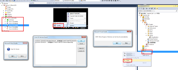
Right-click the IO-Devices of the project, and then scan (if Scan is not available, please switch TwinCAT to Config mode first), and then scan out all the digital and analog input and output
You can first complete the simple digital input and output, and define an array of bool type. Note that the AT%I and AT%Q are added, which are respectively linked to the scanned digital input and output.

Digital output is relatively simple, and can be represented directly using a Checkbox to indicate data (by modifying the Variable's properties to correspond to the array element). During actual testing, checking the box indicates TRUE, while unchecking it indicates FALSE (you can test that the corresponding relay reacts when DO outputs).

Also use a Checkbox to represent numeric input (You can test that when the sensor has input, the corresponding box is checked, and when there is no input, the box is not checked, even if it is manually checked, there will be no response)

For the analog output EL4024, the output is finally converted into 4-20mA data


We can write a simple conversion ourselves (because the data that is actually bound to the port is an INT type, and we only know that we are inputting meaningful data such as 4-20mA. We can modify the Display Scaling to 4-20 on a bound variable to view the corresponding mA value), and we know that the conversion process should be linear. Given a minimum input of 4mA, we should actually give a 0 to the bound INT variable. Given a maximum input of 20mA, we should output a 32767

This is indeed true in actual testing. When AO_0 is given 4-20, it can indeed vary within this data range, and it can be observed that the Online data is also correct.

In the actual connection, I wrote a current value of 13.45mA to the AO_0 port, and it was confirmed to be true using a multimeter

For the analog input EL3054, the input data needs to be converted into 4-20mA data.

The conversion process is similar, except that now we are changing the INT type output of 0-32767 into a 4-20mA output that we can understand. You can see the code for details, which is also derived from the formula y=kx+b.

In the actual connection, I connected a resistor to the AI_0 port and tested the current value with a multimeter. It was indeed consistent with the TwinCAT acquisition.