Quick Startup Guide
This chapter should help over the first steps while working with the Siemens Safety. It cannot replace any basic
training/knowledge of handling/programming the Siemens controllers.
2.1 Settings STEP 7
Basis for this steps, is an installed Step 7 V5.5 version
2.1.1 Set PG/PC interface
Set the PG/PC Interface accordingly to your connection. In this example, an USB LAN adapter is used and set as
PG/PC interface. Please set this accordingly to your connection

To test, you may click on “Accessible nodes”

2.1.2 Set Language/Mnemonics Set English for the language/Mnemonics as this is our
default setting.

Check also in the project, if it is set on Windows language neutral

2.2 Naming modules
There is no fixed topology; therefore no regulation where to connect
the participants among each other. This has the disadvantage that the modules have to be named manually. For this, “Proneta” a free SW from Siemens is recommended. See
chapter 1.1 where to get.
2.2.1 Proneta settings Check the settings for the network adapter; it has to fit the
adapter you are connected to

2.2.1 Network Analysis/Naming To name the module, please just connect your computer to the module and disconnect any other cables. Open up then the Network analysis and refresh ( ) to show the available modules. Double-click on the module and set then the names accordingly to the installation place (see also table below). Repeat for all available devices

2.3.2 Connecting/Mapping
2.3.2.1 Connection settings of your computer Get connected over a TCP/IP switch of the Line. Use a static address in the range of the IPC`s for the network adapter of your computer. Use Subnet mask 255.255.0

2.3.2.2 Map a network drive
On the Start menu, click Computer.
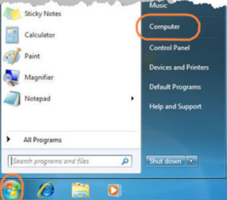
In the next window, click Map Network Drive


Click finish (you need to be connected and connection needs to be ok to be able to finish). Type in the credentials to log in.
2.3.2.3 Open project in Step7 Open the Step 7 Manager. Click Tab File, click Open, then Brows

Browse for the mapped network drive and select the project. Click OK

2.3.3 Retrieving the project If there are no projects on the designated directory, you must get the newest archived project from the server
Those files are zipped, do not unzip, do use the retrieve function within the STEP 7:

If the poject have been retrieved and therefore saved to the proper directory, the name of the project will be wrong, some characters will be deleted automatically. Please rename the folder name, so it does fit to the project and version of the retrieved project
2.4 Hardware Configuration
2.4.1 Check the HW configuration The HW configuration needs to fit the modules installed. Please double-check the configuration with the electrical diagram. Check the type of module, slot Nr and addres

If not ok please change. For the 4 F-DO and 4 F-DI we are using the same types, so you may just delete/copypaste until it fits the electrical diagram. After deleting/replacing a module, please aware, that you have to adjust
the address as well the F destination address again.
Double click on the module, set the address in the tab Address and F Destination Address in tab Parameters

All the inputs or outputs should be activated, you may check if needed on the module parameters. Check
chapter 3.3.4 how to do.
If a complete Interface module (such as CCF/AGJ/BCC..) is missing, you can delete the module or configure it in
the DB2110 GlobDB_Configuration_HW.
Open up the Datablock and set the Initial value true, for the Interface module which has to be deactivated.To
initialize thi changed value, you have to change to “Data view” and initialize the Datablock over the Edit tab (see
also PrntScrn below)

2.4.2 Check available Hardwar
2.4.3 Loading the Software If you have done some changes to the HW configuration, it is recommended that you load the HW configuration and the Blocks. Changes on the HW safety modules change also some Data blocks, as each HW safety module have its own Data block. Follow the steps below: HW configuration: • Open up HW Configuration • Save and compile (PW =1 before Safety acceptance)• Download

Blocks:
• Right-click on blocks
• Click on “Check Block consistency”
• Compile all
• Click Edit safety program
• Download and follow the steps shown below

2.5 Troubleshooting This chapter should help troubleshooting, therefore see some of the common issues listed below
2.5.1 Checking for errors If there are any errors, the CPU will show it on the LED on the CPU Explanation

Go to the HW configuration for further information on the error. Go online . Check for the module with the error. Make sure, you double-click on the safety IO module to get the IO Device Diagnostic. Click Display to show further information about the error

2.5.1 Common errors 2.5.1.1 Parameter assignment error

Parameter assignment error will show up, if the DIP switches on the module do not fit to the set F destination
address in the HW configuration. See chapter 3.3.1 how to do.
2.5.1.2 Module not available

Possible cause for Module not available:
• Connection not ok
• Module configured but not there
2.5.1.3 Error in data message

Error in data message frame will show in most cases if you saved/compiled and loaded the HW configuration, but not the Blocks. Some changes in the HW configuration may also change some Datablocks belonging to safety, so if this error pops up, compile and load the plc blocks as well. See also chapter 2.3.3 how to compile and load
3.3 Hardware Please be aware of the following HW configuration settings
3.3.1 F Destination Address Each safety module has DIP switches to set the F Destination Address. This address has to be the same on the module and in the HW configuration. F Destination address is equal to the start address of the module

3.3.2 Device name The device name of each interface is accordingly to its installation location. Refer also to table in chapter 2.2.1 Example FOL/TB

3.3.3 Addresses Refer to the SW IO Allocation table for the proper addressing. SW Tags are already assigned for all possible addresses.
3.3.4 Module parameter The evaluation for the 2 channel is made within the hardware and therefore to configure in the module parameters. If 2 channels evaluation is needed,
Channel 0/4
Channel 1/5
Channel 2/6
Channel 3/7
of each 4/( F-DI module are a designated pair.
Default settings for Input modules:


Default settings for Output modules
