brief introduction
Introduce the relevant settings, program writing, and precautions of the CX controller of Beifu's 1-second UPS (SUPS) when using UPS for parameter saving.
keyword
1 second UPS
Main text
Main CX products with SUPS
1. CX5000 series,
Mainly CX5010, CX5020
2. CX5100 series,
Mainly CX5120, CX5130, CX5140
3. CX8000 series
Including CX8010~CX8095, there are many controller products with SUPS, and the setting method is relatively similar. However, the CX5000 series is gradually fading out due to its low cost-effectiveness. Therefore, this article mainly focuses on introducing the CX5120, while the other two series are separately pointed out in different places from the CX5120.
The main settings of SUPS
To use a 1-second UPS, you must first configure the settings, and then perform program control. Improper settings or programs in any area can cause abnormal parameter saving. The main settings are:
BIOS settings 2. Operating system settings 3. System manager settings
Points to pay attention to in the PLC program section:
1. Reference to Library 2. Use of Function Blocks and UPS Mode 5. BIOS Settings: Enable the SUPS function in the BIOS, which is enabled by default and does not need to be set under normal circumstances. When problems occur, you can check whether the BIOS settings are correct. The steps are as follows:
1. Connect the monitor and mouse to the controller (BIOS cannot display remotely)
2. Press delete to enter the following screen when turning on the computer

3. Select Power controller Option

Ensure that the red box is checked, and additional options are described below:
Hold USB: Whether to supply power from the UPS to the USB
Delay: The delay charging time of the UPS after power-on. Note that the UPS will start immediately after power-off and cannot be delayed.
In addition, there are some UPS information at the bottom:
Battery Load Level: the current percentage of power of the UPS
Power fail counter: the number of sudden power failures, that is, the number of external power failures
The CX controller settings for Win7 and Win10 systems are divided into two types: WES7 systems (sometimes referred to as Win7 systems) and CE systems.CE systems do not require any operating system settings, while Win7 and Win10 systems require attention to disk write protection features. This is because the power-down parameter storage mechanism for Beckhoff CX is to write a file to a specific path on the hard drive. Once write protection is enabled, this file cannot be saved, meaning that the parameters will return to the boot state.
1. EWF protection system
EWF: Enhanced Write Filter, which is disabled by default. If the program needs to maintain parameters online during power loss, this feature needs to remain disabled.Note: After changing the EWF status, it needs to be restarted to take effect, so it is necessary to restart every time after making changes.When EWF is enabled, all program data will be transferred to RAM once at startup, without any write operations to ROM, so the ROM data remains unchanged after power loss.In addition, this can greatly improve the lifespan of the storage card.
2. FBWF
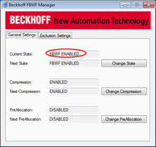
FBWF: File Based Write Filter, file-based write protection. FBWF is also disabled by default and can be left off. If you need to save power-down data after turning it on, you need to set the power-down data as an exception, as shown in the following figure. Note the settings in the red circle.
3. UWF
UWF is a write protection tool provided by Microsoft and is only available with the Win10 package. The Beckhoff version of the UWF operating interface is shown below. For setting methods, please consult Beckhoff technical personnel.Keep the parameters at their default values to ensure that the parameters function properly during power loss.
Setting of Systemmanager
This setting is relatively simple, by checking the corresponding boot program and clearing invalid persistent data in the PLC settings. However, it is not a big deal to not clear the data, as the system will automatically use the backup data file when it detects an invalid data file.Also, when the program saves data, it will overwrite the original power-down data file.

The mechanism of data storage in 1 second UPS

1. It can be seen that the controller with SUPS will save data and perform a quick shutdown after powering off. This shutdown is much faster than a normal shutdown.And the first step after booting will load data.It has the following characteristics:
The 2.1 second UPS is essentially a capacitor. Over time, the capacity of the capacitor decreases, and the duration of power outage is also shortened.Normally, it is more than 3 seconds.
3. You can only store up to 1MB of data
4. SUPS does not supply power to Kbus, Ebus, Ethernet ports, or other buses
In TC2, the power-down data file is located in C:\TwinCAT\Boot\.TCPLC_T_x.wbp is the power-down data file, and TCPLC_T_x.wb~ is the power-down data backup file.Typically, there is no need to rename them;
6. In TC3, the power-down data file is located in C:\TwinCAT\3.1\Boot\Plc, Port_85x.bootdata is the power-down data file, and Port_85x.bootdata-old is the backup file of the power-down data;
Different PLCs require different library files for their PLC libraries and corresponding function blocks:
1. The CX5120 needs to call TCSUPS_CX51x0.lib, and the calling function block is FB_S_UPS_CX51x0;
2. The CX5020 needs to call TCSUPS.lib, and the calling function block is FB_S_UPS;
3. The CX8090 needs to call TcSystemCX80xx.lib, and the calling function block is FB_S_UPS_CX80xx;
The wrong call of the library file and the mismatch between the function block and the physical object will lead to the failure of the power-down save function. A large number of engineers use the wrong library file and function block, resulting in the UPS not working.Ten, writing programs The two core functions of the program are to set the working mode of the UPS and obtain the online status of the UPS.Although the hardware of the three different types of controllers is different, the interface of this function block is the same, only the hardware driven by the background is different. Here, CX51x0 is selected for explanation.
1. Acquire the status of UPS
After calling the UPS library file, a global variable (defined inside the library file) is automatically obtained as follows:
eGlobalSUpsState: E_S_UPS_State;(*current ups state*) The current UPS state, which can be directly used in the program. Various state descriptions are as follows:
1) eSUPS_PowerOK: external power supply is normal
2) eSUPS_PowerFailure: External power failure (this state will only last for 1 PLC cycle)
3) eSUPS_WritePersistentData: Writes the power-down persistent parameters (see Chapter 8 for details about the UPS power-down and startup process)
4) eSUPS_QuickShutdown: The system starts to quickly shut down
5) eSUPS_egasForRecover: Wait for external power supply recovery
6) eSUPS_ WaitForPowerOFF: Wait for the UPS to power off when the battery is exhausted
2. Setting of UPS working mode
Call the FB_S_UPS_CX51x0 function block to set the relevant mode

1) sNetID: The local control can be empty
2) iPLCport: TC2's default is 801
3) iUPSPort: CX51x0 series is 16#588, CX50x0 and CX8000 series is 16#4A8
4) tTimeout: can be left blank
5) eUpsMode: This is a core parameter with four modes:
a) eSUPS_WrPersistData_Shutdown: Save data and then perform a quick restart.Note that only win7 and win10 systems select this option. If the CE system selects this option, it will trigger a restart (CE system does not shut down). After restarting, power loss may cause data loss, which is a waste of effort!b) eSUPS_WrPersistData_NoShutdown mode, after saving data, do not shut down.Only the CE system selects this option, after saving data, wait for the UPS to run out of power and shut down.c) eSUPS_ImmediateShutdown mode, immediately shut down without saving data.d) eSUPS_CheckPowerStatus mode, only checks the status, does not save data and shut down.6) ePersistentMode:
SPDM_2PASS
7) tRecoverTime: The secondary start-up time. When the external power is cut off, the UPS is activated, and even if the power supply is restored at this time, the UPS will still shut down the system.After tRecoverTime has elapsed since the power supply was restored, the system will automatically start up.Therefore, this time is preferably longer than the time the UPS can sustain. It is recommended to set it to 10 seconds to 30 seconds, that is, after the external power is cut off and restored, the PLC saves the data and then shuts down, and then after x seconds, the system restarts again, rather than restarting immediately or not restarting.
Common Problems
1. Is it necessary to write Persisternt data in the program cycle, as shown in the following figure:

A: There is no need for circular writing, and a manual trigger for writing once can be added.When the external parameter value changes, manually trigger it once.Normally, this function block is used for controllers without a 1-second UPS to save persistent data. Controllers with a 1-second UPS do not need to use this function block, and the system will automatically save it during power failure (see the shutdown process in paragraph 8).