Executive Summary
1. Trigger mechanism of NC axis fault 0x4655 (18005)
2. Trigger mechanism of servo alarm Sync Lost (0xF415)
3. Basic methods and sequence of troubleshooting on site
Keywords:
4655,18005,F415,Sync Lost,WcState, Data Invalid
scope of application:
When using TwinCAT NC to control servo drives, the NC axis alarm 0x4655 (18005) is triggered, while the Beckhoff servo drive AX5000 also reports an alarm 0xF415, or a third-party drive reports an error of "loss of synchronization".18005 and F415 may be alarm codes triggered by the same hardware failure on the EtherCAT master side and slave side, respectively.This article describes the mechanism of fault triggering, lists possible causes, and provides troubleshooting methods and sequences.This article also applies to the handling of Data Invalid exceptions in common IO slave WcState.
Text:
1. Trigger mechanism of NC axis fault 0x4655 (18005)
1.1 Alarm information and related phenomena
(1) Fault information:
Invalid IOdata for more than 'n' continuous NC cycles, which means that the data of the servo driver is invalid for several consecutive NC cycles.
(2) Fault phenomenon
When NC reports 18005 (Invalid Data), the current position displayed on the NC axis Online page is gray, and the servo's CoE Online will be disconnected, displaying only Offline Data.After MC_Reset, the CoE Online will return to normal.
(3) Basis for NC alarm
For EtherCAT servo, NC automatically detects whether the data is valid through the slave's WcState status bit

(4) Relationship between WcState and synchronization unit SyncUnit
The generation mechanism of WcState is related to the synchronization unit (SyncUnit).According to the configuration of the master station, each EtherCAT Frame includes several SyncUnits, which in turn contain several slaves.If the IO refresh fails when the Frame passes through a slave, all modules WcState under the SyncUnit to which the slave belongs will be set to TRUE, indicating that the data is invalid (Data Invalid).
According to the default settings of TwinCAT, all slaves under a Frame are in the same Sync Unit, so by default all servos on an EtherCAT network belong to the same Sync Unit, and all suffer together.
1.2 What are the conditions that cause the refresh failure of the IO slave
Why does the IO refresh fail when Frame passes through Slave?There are two possibilities: either Frame didn't come or came late, or the data is corrupted, or Frame is normal but Slave has its own problems and cannot extract or insert data from Frame.
1.2.1 When did Frame not come?
For the slave station, the Frame is not received, which is called Frame Lost on the master side.This can be monitored on the EtherCAT Online interface:

The reason for frame loss is not necessarily that the master station did not send the frame. As long as the frame was sent, it will not be lost in thin air. More likely, the data was corrupted, so the slave station received "unqualified" frames after the point of corruption.According to the location and time of the corruption, it is classified and counted in the Lost Frames or Tx/Rx Error counters.For the slave station, it is equivalent to not receiving the frame, and this error is often caused by hardware.
1.2.2 When is Frame late?
The so-called late arrival refers to the "scheduled" time.Only the slave station working in DC Sync Mode needs to set the "scheduled" time for the arrival of the frame.The following figure shows the timing relationship between the master station program, EtherCAT transmission, and the slave station program.

In the figure, Master is TwinCAT and Slave is the servo drive.Taking the task with a 2ms cycle as an example, TwinCAT performs an operation every 2ms and then sends a data packet.The servo also extracts data from the data packet every 2ms, so it must ensure that the Frame passes through the servo before the servo extracts the data.Conversely, the data packet must arrive before the servo cycle starts.Therefore, the operation cycle points of the master and slave stations must be offset, which is the Shift in the figure above.
TwinCAT will automatically set this Shift value. If the Frame does not arrive before this Shift, it is called "late".The slave station is called a refresh failure in this cycle, which is reflected in the WcState as Invalid Data.
1.2.3 Why can't the slave refresh the data?
The slave application regularly extracts the data sent by the Frame from its EtherCAT cache.If the data in the EtherCAT cache is normal but the slave application cannot process it, it must be a problem with the slave itself, such as insufficient voltage, unstable operation, internal chip issues, interference issues, and the like.
1.3 Why does the PLC not report "Invalid IO data"?
Why does the NC task always report "Invalid IO data" but the PLC does not report this error?
Due to safety considerations, if the NC axis has detected that the WcState is invalid for three consecutive cycles, which is 6ms in length, the motor is prohibited from continuing to operate.This is because when the WcState is invalid, the servo status word detected by the NC cannot represent the actual status of the servo, and continuing to operate may be dangerous.Depending on the actual process requirements, it is also possible to disable the NC axis from detecting the WcState to expand fault tolerance.
On the other hand, PLC programs require human intervention to add detection of WcState and write corresponding safety processing procedures.If the input data of the IO module does not accurately reflect the state of the on-site sensor, then the PLC code performing calculations based on the input data and controlling the actions of the output mechanism may potentially pose a danger.Considering that PLC programs have lower real-time requirements than NC, the time limit for continuous invalid triggering alarms can be extended.
2. Trigger mechanism of servo alarm Sync Lost (0xF415)
Note 1: This paragraph is taken from the AX5000 manual in Beckhoff Infosystem.
Note 2: The same Sync Lost alarm has different fault codes for different servo systems. The fault code for the Beckhoff AX5000 servo is 0xF415, the fault code for the Omron servo is 83, and the fault code for other brands of servo is different.The following discussion refers to this type of fault as F415.
Note 3: The slave station reports Sync Lost, which means that the frame from the master station did not arrive on time or the data was damaged when it arrived.
2.1 Mechanism of EtherCAT synchronization
Note: This synchronization mechanism also applies to other EtherCAT slaves with distributed clocks, such as third-party servos.
The EtherCAT master sends EtherCAT messages to all slaves.Each slave has a dedicated EtherCAT message processing unit, called the EtherCAT slave controller (ESC).In order to achieve high positioning accuracy and meet strict requirements for concentricity characteristics, the master and all connected servo drives should maintain synchronization in generating setpoints.In the EtherCAT system, this synchronization task is achieved through distributed clocks.

2.1.1 EtherCAT Master
When TwinCAT generates the configuration, System Manager automatically completes the basic settings of the distributed clock (DC) parameters for the connected EtherCAT slaves based on the TwinCAT project and ESI file.
When the EtherCAT network starts up, it sends the Init initialization command to transfer these parameters to the slave station without manual intervention.The default settings should be modified only after consulting AX5000 technical support.
2.1.2 EtherCAT slave controller (ESC)
The EtherCAT slave controller (ESC) of the AX5000 generates two synchronization signals (Sync0 and Sync1) based on the configuration of the master station (in TwinCAT).The CPU of the AX5000 analyzes these two synchronization signals and synchronizes them with internal control calculations.
2.1.3 Sync0
The Sync0 signal is triggered by default every 250us. If the Sync0 trigger fails (see F0), the CPU reports an F414 error.The motor stops according to the emergency stop deceleration curve.
- Related alarm information:
The Sync0 cycle can only be set to 62.5 μs, 125 μs, or 250 μs, otherwise the CPU will report an F409 error;
If the Sync0 signal in ESC is not activated, the CPU reports an F410 error.
If the interrupt pulse width is insufficient, the CPU will report an F411 error
In case of any of the above errors, the motor will stop according to the emergency stop deceleration curve.
2.1.4 Sync1
The cycle of the Sync1 signal is determined by the NC cycle, and it is always an integer multiple of Sync0.If the Sync1 signal cannot be triggered (see F1), the CPU will also report an F414 error, and the motor will stop according to the emergency stop deceleration curve.
- Related alarm information:
The Sync1 cycle must be an integer multiple of Sync0 and the same as parameters S-0-0001 and S-0-0002, otherwise the CPU will report an F412 error.
If the Sync1 signal in ESC is not activated, the CPU will report an F413 error.
If the interrupt pulse width is insufficient, the CPU will report an F411 error
If any of the above errors occur, the motor will stop according to the emergency stop deceleration curve.
2.1.5 End of telegram (EOT)
The EtherCAT status controller (ESC) in the station dynamically processes EtherCAT messages. After detecting the End of Transmission (EOT) marker at the end of the message, if the message is sent to the station and no CRC error occurs, it transfers the message content to the specified synchronization manager SyncManager2, and then sets the status of SyncManager2 to 'SyncManagerwritten'.When Sync 1 is triggered, if the status of SyncManager2 is 'SyncManagerwritten', the CPU of the AX5000 will copy the data from SyncManager2 to its own memory area.
The CPU requires that the data in SyncManager2 has been refreshed when the Sync1 event is triggered, so the EOT flag must be detected before Sync1 is triggered. Otherwise, the CPU will not replicate the data.If there is no data replication during two consecutive Sync1 events, the AX5000 will report an F415 error and the motor will stop according to the emergency stop deceleration curve.
- Jitter!
Due to "jitter" and other reasons, it is necessary to ensure that new data is received within the specified time.The EtherCAT master must ensure that the data arrives at SyncMan2 (Synchronization Manager 2) in a timely manner.

In the figure above, EtherCAT messages pass from left to right, and the last BIT is the EOT marker. The left side is the normal case: the Sync1 pulse is detected after a period of time (DT2) after the EOT marker.The right side is the error case, where the Sync1 pulse occurs before the EOT marker.
2.2 Fault examples
The AX5000 drive continuously monitors the real-time performance of the device during operation, with one important monitoring target being the synchronization performance of all hardware and software components in the data transmission link.The following simple illustration illustrates this data transmission process, with a focus on the "NC" drive task and the "PLC" general logic task.
2.2.1 Sample 1
(1) Basic conditions
1. The CPU timer of the TwinCAT controller sends interrupt signals at a fixed time base (default: base time = 1 ms)
2. Execute each task in order according to the priority management principle of multitasking
3. Task management:
Due to the increase or decrease in the amount of PLC calculations, the task occupancy time increases or decreases accordingly. Therefore, the "I/O update" should be set to "At task beginning", which eliminates the potential for a synchronization error.
Unreasonable task prioritization is another potential pitfall of synchronization errors.
4.After the "I/O Update", the generated data is transmitted to the TwinCAT IO system, and then sent to the connected devices by EtherCAT telegrams.The EtherCAT telegrams pass through each physically connected device and transmit or receive data from the device.
5. The priority of a task determines its execution order. First, the high-priority task is executed and data is sent to TwinCAT IO. Then, TwinCAT IO sends EtherCAT messages.When there are multiple tasks with different cycles in the system, problems can arise if the priority is not arranged properly, as shown in the figure:

(2) Priority setting
The following describes the impact of priority settings on data synchronization,
- Assuming (PLC priority is higher than NC):
Sync1 = 3ms
NC cycletime = 3 ms
NC priority= 10
PLC cycletime = 2 ms
PLCpriority = 5
NC data needs to be transmitted to the drive periodically, but when the PLC is occupying computing time, no data is transmitted to the drive.
Due to their higher priority, PLC tasks are always calculated before NC tasks;these tasks interact with each other at the starting point time of "0 ms" and then repeat every "6 ms", which is 2x Sync1.The ESC of the drive requires that the EtherCAT message send NC data at every Sync1 signal (3ms).However, this cannot be guaranteed because the higher priority PLC tasks are always calculated before NC tasks, so the message sending delay occurs during synchronization mapping (Sync Mapping).This causes a NC message delay every 6 milliseconds, which may lead to an F415 error in the AX5000.

2.2.2 Sample 2
(1) Basic information
1. The CPU timer of the TwinCAT controller sends interrupt signals with a fixed time base (default: base time = 1 ms)
2. Execute each task in order according to the priority management principle of multitasking
3. Task management:
Due to the increase or decrease in the amount of PLC computation, the task occupancy time increases or decreases accordingly. Therefore, the "I/O update" should be set to "At task beginning", which eliminates the potential for a synchronization error.
Unreasonable task prioritization is another potential pitfall of synchronization errors.
4.After the "I/O Update", the generated data is transmitted to the TwinCAT IO system, and then sent to the connected devices by EtherCAT telegrams.The EtherCAT telegrams pass through each physically connected device and transmit or receive data from the device.
5.The priority of a task determines its execution order. First, the high-priority task is executed and data is sent to TwinCAT IO. Then, TwinCAT IO sends EtherCAT messages.When there are multiple tasks with different cycles in the system, problems can arise if the priority is not arranged properly, as shown in the figure.

(2) Priority setting
The following describes the impact of priority settings on data synchronization,
- Assuming (NC has higher priority than PLC, both are Sync Mapping and drive DC slave):
Sync1 = 3ms
NC cycletime = 2 ms
NC priority= 5
PLC cycletime = 3 ms
PLCpriority = 25
NC tasks only handle devices in SyncUnit 1, synchronous mapping
The PLC task only processes devices in SyncUnit 2, synchronous mapping
Both NC and PLC data need to be transmitted periodically.
Due to their higher priority, NC tasks always execute before PLCs and send messages first.These tasks interact with each other at the starting point time of "0 ms" and then repeat every "6 ms", which is 2x Sync1.However, the ESC of the drive requires an EtherCAT message every sync1 (3 ms).This is not a problem in SyncUnit 1, where NC provides services, because high-priority NC always sends messages at the same cycle, but the PLC message may experience a delay every 6 milliseconds, which may cause the AX5000 in SyncUnit 2 to encounter an F415 error.

3. Basic methods and sequence of troubleshooting on site
Due to the NC axis fault 0x4655 (18005) and the AX5000 fault 0xF415, which are simply the same issue causing alarms on the master and slave sides, the following processing methods are applicable to both alarms and can also be used in situations where the PLC detects a WcState of Invalid Data.The basic content is:
a) Analyze the nature of the fault: software fault or hardware fault
b) Removal methods for hardware faults
c) Software fault elimination method
3.1 Analyze the nature of the fault using diagnostic tools
Using the EtherCAT diagnostic interface integrated with TwinCAT, it is possible to roughly locate the cause of the fault, whether it is due to hardware or software.
(1) EtherCATOnline
The Online interface of the EtherCAT master station can display the hardware fault counts of the master and slave stations:

The CRC check can detect hardware errors in slave devices. Common modules have only two columns, with the left column indicating the number of CRC errors at the entrance and the right column indicating the number of CRC errors at the exit.For EL modules, the left E-Bus contact is the entrance and the right E-Bus contact is the exit.For EtherCAT drives, both the left and right inbound and outbound connections can have CRC errors, depending on the slave device specifications.The location of the CRC error can be used to locate the most likely source of interference or failure.
If the values inside the red box in the above figure are all 0, it indicates that there is no problem with the hardware and that the fault is in the software.
(2) Main station DC diagnosis
Another tool for detecting communication quality is Distributed Clocks|Diagnosis in the Advanced Settings of the master station, also known as Jitter detection:

In the above image, the sudden increase in frames with a jitter greater than 500us can be determined to be a hardware failure.However, the steady increase in counts for frames with a jitter less than 500us is caused by software settings such as shift time or PLC.
3.2 Hardware failure causes errors or loss of EtherCAT Frame
Strictly speaking, the Frame loss mentioned here refers to the situation where the slave station does not receive a "legal" Frame, including both Frame Lost and Frame Error.Frame loss is usually caused by hardware, including controllers, network cables and connectors, IO modules and servo drives, as well as power supplies, shields, and external interference sources.For example, the four contacts of the EtherCAT connector are sometimes on and sometimes off, with some on and some off. This kind of failure is often related to the production status, such as errors when the device is turned on, high-speed motion, high temperature (summer daytime), and errors reported after several months or even a year or two of production at the end user's site.
Note: Completely unplugging the network cable will not cause frame loss, as the previous slave can detect whether the network cable is unplugged. If it is found to be blocked, it will automatically return to the original path. A slave that continues to detect no frames will switch back to the init state, rather than reporting a loss of synchronization.
3.2.1 Basic requirements for hardware fault troubleshooting
(1) Power supply
Check whether the voltage and power of the control power supply meet the requirements.When the voltage or power is insufficient, a communication error may sometimes be reported.
For example, the AX5000 requires a control voltage tolerance of +-25%. Considering the aging of the switching power supply after a period of use, the actual output voltage will decrease, and if the line from the switching power supply to the drive is long, the voltage drop cannot be ignored. Therefore, according to experience, the output voltage of the switching power supply will be adjusted to 26.5V at the beginning of debugging.Every time the switching power supply is checked thereafter, it will be adjusted to this value as much as possible.

(2) Shielding and grounding
When the shielding and grounding are not reliable, it is easy to have EMC interference.Check whether the drive grounding is good.
The entire EtherCAT network should share a common ground, otherwise the circulation between different grounds can cause communication data corruption.

In addition, adding magnetic rings to EtherCAT network cables helps improve anti-interference capabilities, and adding magnetic rings to the power lines of third-party servos helps reduce EMC interference with external devices.
Other EMC rules...
(3) Network cable and connector
- The quality of the network cable and connector
First, use professional industrial network cables and connectors, preferably Beckhoff's pre-made EtherCAT cables.If customers purchase Beckhoff cables and connectors to press their own wires, they should ensure that the shielding layer is firmly in contact with the metal housing.
It is forbidden to use cheap network cables and crystal heads to make EtherCAT communication cables by yourself. If this situation is found at the troubleshooting site, it is necessary to specifically check whether the network cable is shielded and whether the shielding layer is in good contact with the connector.
If conditions permit, use Beckhoff prefabricated network cables to replace the ones with doubts one by one.
- Firmly installed
Check the network cable connector for oxidation.
Check the drive network port: whether it is damaged, the contact spring is not strong enough, deformed, or oxidized.
After connecting the network cable, it is best not to stress the network port, otherwise the network port is prone to deformation.
Shake the network cable, check whether the plug is loose, whether there is an alarm, and replace the network cable.
3.2.2 Software basic configuration check
(1) Whether the current of Ebus is sufficient
Check whether the EBus current of the IO module is sufficient. If the module and the driver are both on the same EtherCAT network, some IO problems may cause EtherCAT data to not be returned to the master station, and all drivers will report loss of synchronization.
(2) The configuration file matches the actual installed hardware
The easiest way is to rescan the IO and compare it with the configuration in the project file to see if it is consistent.
In fact, TwinCAT also integrates a tool called "Emergency Scan for Master Station".Using Emergency Scan, you can verify whether the offline configuration is consistent with the online configuration.The method is as follows:
In TwinCAT Config Mode, performing an Emergency Scan can send a predetermined number of probe data frames for rapid testing of permanent hardware problems (device, cable, or connector damage) in physical connections, but this method is difficult to detect random interference.
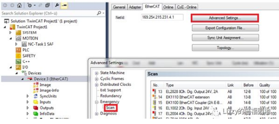
If the actual IO module and slave are consistent with the configuration, the last column "Quality" in the above figure will always be 100 of 100, indicating that 100 successful returns were received after 100 transmissions.If it is 0 of 100, it certainly indicates that the configured module or slave does not exist.If it is less than 100, it indicates that some data packets did not return successfully, and most likely there is a problem with this slave.
3.2.3 Basic optimization of software configuration
(1) Each servo driver is equipped with an independent synchronization unit
This is to eliminate the possibility of individual drives causing errors that affect other drives and also reporting Data Invalid. However, EtherCAT treats these slave devices that report Data Invalid equally, causing harm to innocent devices.
(2) Clear the variable mapping between the WcState of the servo and the NC axis
The default NC detects that the WcState is TRUE for 3 SAF cycles of connection, and triggers the 18005 alarm.However, some third-party slave stations may have a higher number of fault tolerance for Sync Lost than the NC. As a result, the NC reports the alarm before the servo does.Therefore, the NC no longer sends new data (at this time, the current position seen on the Online page of the NC axis is gray, and the CoE Online page of the servo only displays offline data), causing the servo alarm.MC_Reset is required to recover.
- Limitations of Sync Unit
If the Frame is missing, delayed, or corrupted, all slave or latter half slave nodes will fail IO refreshing no matter how the Sync Unit is set.If the Frame is normal but the slave itself has a problem, setting each server to an independent synchronization unit (preferably in conjunction with the star topology and HotConnect settings) will help pinpoint the faulty slave.
3.2.4 EtherCAT Link Optimization
(1) Try to place the servo in the front of the EtherCAT link
The closer it is to the front, the less likely it is to be affected by the IO module, which is beneficial.
(2) Optimal solution: separate IO and drive into two EtherCAT networks
At the beginning of electrical design, if there are many drives and the cost budget and installation space allow it, it is recommended to separate the servo drive and the ordinary IO, each using a separate EtherCAT network.
The CX50, CX51, and CX20 series EPCs have two separate network cards on the left side in addition to the built-in EtherCAT on the right side, one of which can be used to run EtherCAT with servo drives.
For IPCs such as C60 and C69, although there are two independent network ports as standard, one is used for programming and external Ethernet communication, and the other is used for EtherCAT. If IO and drives need to be separated into two EtherCAT networks, the CU2508 network multiplier needs to be added.
(3) Suboptimal solution: use star topology as much as possible
Use star topology (increase EK1122 or CU1128) as much as possible.
3.2.5 Other Notes
(1) Problems with the network card of the master station
The controller network card or driver may have a problem. If it is a third-party industrial computer or a controller with many other installed drivers, it may also have problems and be unstable.
(2) Focus on checking the first slave station that reported Sync Lost
3.3 EtherCAT Frame delay caused by software reasons
Frame is late, usually caused by software:
The first is that the Time Shift between the EtherCAT master and slave stations is not enough;
Second, the task priority is unreasonable;
Third, the fluctuation of program computation;
Another uncommon error is the disorder of the DC master clock.
Software-induced Frame latencies typically do not involve packet loss, TxRxError, or other accumulations, and are unrelated to the production status of the device. The farther back in the link, the more likely it is to report errors.Errors are usually discovered during the factory debugging stage, rather than being reported after production at the end user's site for some time.
3.3.1 Time Shift optimization of EtherCAT master and slave stations
The so-called "late arrival" of the Frame refers to the time relative to the "scheduled" time.Only the slave station operating in DC Sync Mode needs to set the "scheduled" time for the arrival of the Frame.The following diagram shows the time relationship between the master station program, EtherCAT transmission, and the slave station program:

In the figure, Master is TwinCAT and Slave is the servo drive.Taking the task with a 2ms cycle as an example, TwinCAT performs an operation every 2ms and then sends a data packet.The servo also extracts data from the data packet every 2ms, so it must ensure that the Frame passes through the servo before the servo extracts the data.Conversely, the data packet must arrive before the servo cycle starts.Therefore, the operation cycle points of the master and slave stations must be offset, which is the Shift in the figure above.
For a specific slave station, this shift consists of two parts: one is the offset set by the master station that applies to all DC slave stations, and the other is the "extra" offset set individually by individual slave stations.The sum of the two is the offset time of the slave station's application starting point relative to the master station.Within this time frame, the Frame must depart and arrive at the DC slave station, otherwise the slave station will report Sync Lost.
- SYNC Shift Time setting of EtherCAT master station
The "SYNCShift Time" parameter in the lower right corner of the Distributed Clock interface in the Advanced Setting of the EtherCAT master station:

The 30% in the above figure indicates that the application cycle of all DC slaves must begin 600us after the start of the master cycle (taking the task cycle of 2ms as an example).Since NC tasks are by default refreshed after IO operations, the NC task will send an EtherCAT Frame as soon as it starts. As long as the Frame reaches the last DC slave within 600us, the Frame is not late.
- From the setting of Shift Time
From the DC settings of the station, you can set your own "extra" offset, which is superimposed on the Shift Time of the master station, and is the actual offset time relative to the starting point of the master station's task.

3.3.2 Solutions for unreasonable priorities
As mentioned earlier, when there are multiple tasks with DC slaves in the system, Frame will be periodically "delayed" by the least common multiple of the multiple DC tasks. If the task period is short and the number of slaves is large, the Frame sent by the low-priority task is more likely to be late, and the DC slave that is synchronized with it is more likely to report Sync Lost.
Sync Lost caused by unreasonable priority will occur during the first online debugging, which is easy to detect and solve.The method is:
(1) Ensure that tasks with short cycles have high priority
Ensure that tasks with short cycles have high priority by selecting "Auto Priority"
(2) Optimization principles for multi-task-driven slave stations
For tasks with different cycles that require driving DC slave stations, delays are almost inevitable. To address this, there are three optimization points:
a) Only one synchronous mapping is retained,
b) Alternatively, place all slave stations that require DC synchronization into one task.
c) Alternatively, set the shift time for the slave of the low-priority task individually, leaving enough time margin so that its frame can still arrive before the slave's requested time when it is executed last.
3.3.3 Solution to program calculation fluctuation
For PLC programs, fluctuations in the amount of computation per cycle are normal.Overcoming the impact of fluctuations in computation can be done in two ways:
(1) Enable I/O at task beginning
The interface in TC2 is as follows:

In TwinCAT 3, both PLC tasks and C++ Modules do not provide the tag "IO at taskbeginning".
At this time, you can use the attribute TcCallAfterOutputUpdate to achieve the same function:

(2) Confirm that the PLC program operation did not continue to time out
The system variables lastExecTime and cycleTimeExceeded provided by TwinCAT PLC can be used to observe fluctuations in the execution of PLC tasks.The methods for viewing these two variables in TC2 and TC3 are as follows:
Task execution information in TwinCAT 2:

Task execution information in TwinCAT3:

- The impact of lastExecTime fluctuation
For PLC tasks, the default is to calculate first and then send the Frame. If there is a particularly large amount of computation in some cycles, the time to send the Frame may be later than usual, resulting in the Frame not reaching each DC slave before the set Shift Time.Therefore, it is important to set "IO at task beginning" in the PLC task for frames with DC requirements, to avoid Frame delays caused by fluctuations in PLC computation.
In addition to monitoring lastExecTime in the PLC program, you can also roughly see the fluctuation of execution time from the Online section of the Task:

- the impact of cycleTimeExceeded
When cycleTimeExceeded is set once, Frame will be sent less than once, and DC slave stations will not receive Frame for one cycle.For most common modules, occasional loss of one Frame is acceptable, but for some sensitive DC slave stations, or for XFC channels that need to be output during this cycle, there will be adverse consequences.
Usually, when a task timeout (cycleTimeExceeded) occurs, the CPU utilization will reach or even exceed the limit set by Realtime, which is 80% by default.Therefore, directly observing the CPU utilization can also estimate whether a task timeout has occurred:

If a continuous task is detected to have timed out, it is necessary to find the cause and optimize the program.
(3) A testing method: create a new Additional Task to refresh IO
To troubleshoot Frame lateness or missing issuance caused by fluctuations in PLC computation, you can create a new high-priority, Auto Start Additional Task to refresh IO, and place the variables that need to be linked to the DC slave under this task.This will completely eliminate the impact of fluctuations in PLC computation.
Tip 1: If it is verified that the Frame is late or missing not due to fluctuations in the PLC's computation load, it is best to restore the original state by deleting the temporarily added Task and restoring the variable link to the PLC task.
Tip 2: If you are not a user with in-depth knowledge of Task, Mapping, and EtherCAT communication mechanisms, please try to use the "General" and "Default" configurations.If you want to make modifications, you should fully understand the reasons for doing so and the possible associated results.


3.3.4 DC reference clock disorder
If the customer temporarily modifies the hardware configuration, such as disabling the EtherCAT slave as the reference clock, or restarting the EtherCAT slave as the reference clock separately during the normal operation of the controller, it will cause DC clock disorder, making it impossible to determine whether the Frame is on time or late.
If it is detected that the master clock is disabled, specify a different master clock to update the configuration and reactivate it.
If it is detected that the master clock has been powered off and restarted, restart the EtherCAT master station (power-off restart or switch status OP-Init-OP)